
About aim42
aim 42 supports software evolution, maintenance, migration and improvement - in a systematic and pragmatic way.
|
aim42 is a collection of practices and patterns to support software evolution, modernization, maintenance, migration and improvement of software systems:
aim42 seamlessly integrates with your day-to-day development work. |
Authored by the aim42 community, lead by Dr. Gernot Starke <gernot.starke@innoq.com>
![]()
![]()


1. Introduction
1.1. Overview
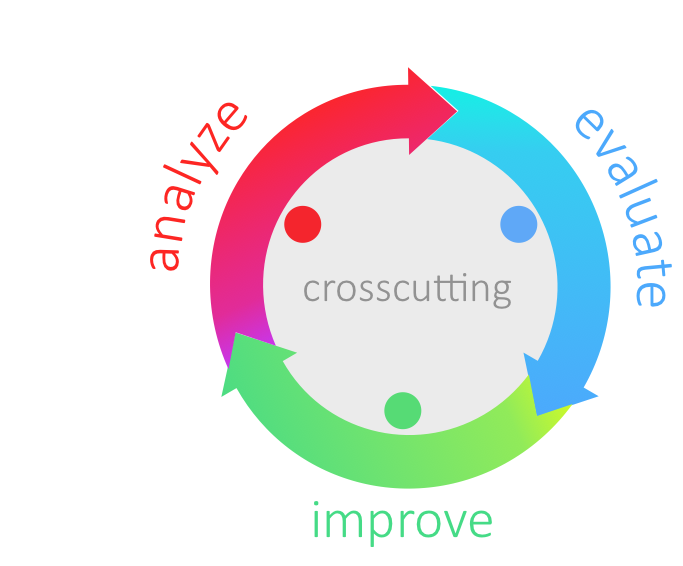
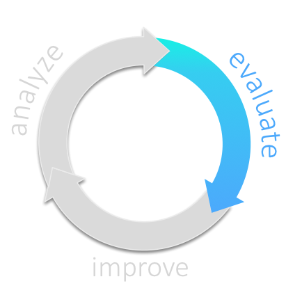
aim42 organizes software improvement in three major phases (Chapter 2, Analyze, Chapter 3, Evaluate and Chapter 4, Improve), build around some crosscutting activities.
Analyze |
Evaluate |
Improve |
Understand the system |
Estimate issue cost: How grave is this problem? |
Improve architecture and code |
Find issues and risks |
Estimate improvement cost: How expensive is this change? |
Improve processes |
Collect improvement options |
Usually "evaluation" means estimation |
Improve technology |
Interview stakeholders |
Estimate in intervalls |
Improve (technical) concepts |
Analyze context |
Evaluate tradeoffs |
|
Analyze architecture and code |
||
Crosscutting |
||
Manage issues (risks, problems, symptoms, root-causes) |
||
Manage improvements |
||
Manage the (m:n) relationships between issues and improvements |
||
Plan improvements, interleaved with to day-to-day activities |
||
Verify improvements (check if improvements resolved appropriate issues) |
||
1.2. Why is software being changed?
Software systems, at least most of those that are practically used, are changed all the time. Features are added, modified or removed, user interaction is streamlined, performance is tuned, changes to external interfaces or systems are reflected. The reasons for changing a system can be grouped into four categories (see [ISO-14764]):
-
Corrective changes
-
fixing failures within the software system
-
-
Adaptive changes
-
data structures we rely on have been changed
-
external interfaces have been changed - our system has to cope with these changes
-
some technology, framework or product used within the system is not available any longer and needs to be replaced
-
-
Perfective changes
-
operational costs have to be reduced
-
maintenance costs have to be reduced
-
existing documentation does not reflect the truth (any more)
-
resource consumption needs to be optimized
-
system needs to work faster
-
system needs to become more reliable or fault-tolerant
-
people need new features
-
system needs to be integrated with new neighbour
-
system needs to comply to new regulations or laws
-
system needs new or improved user interface
-
existing features have to be modified or removed
-
-
Preventive changes
-
technical debt has to be reduced
-
You see - lots of good reasons :-)
1.3. Why does software need improvement?
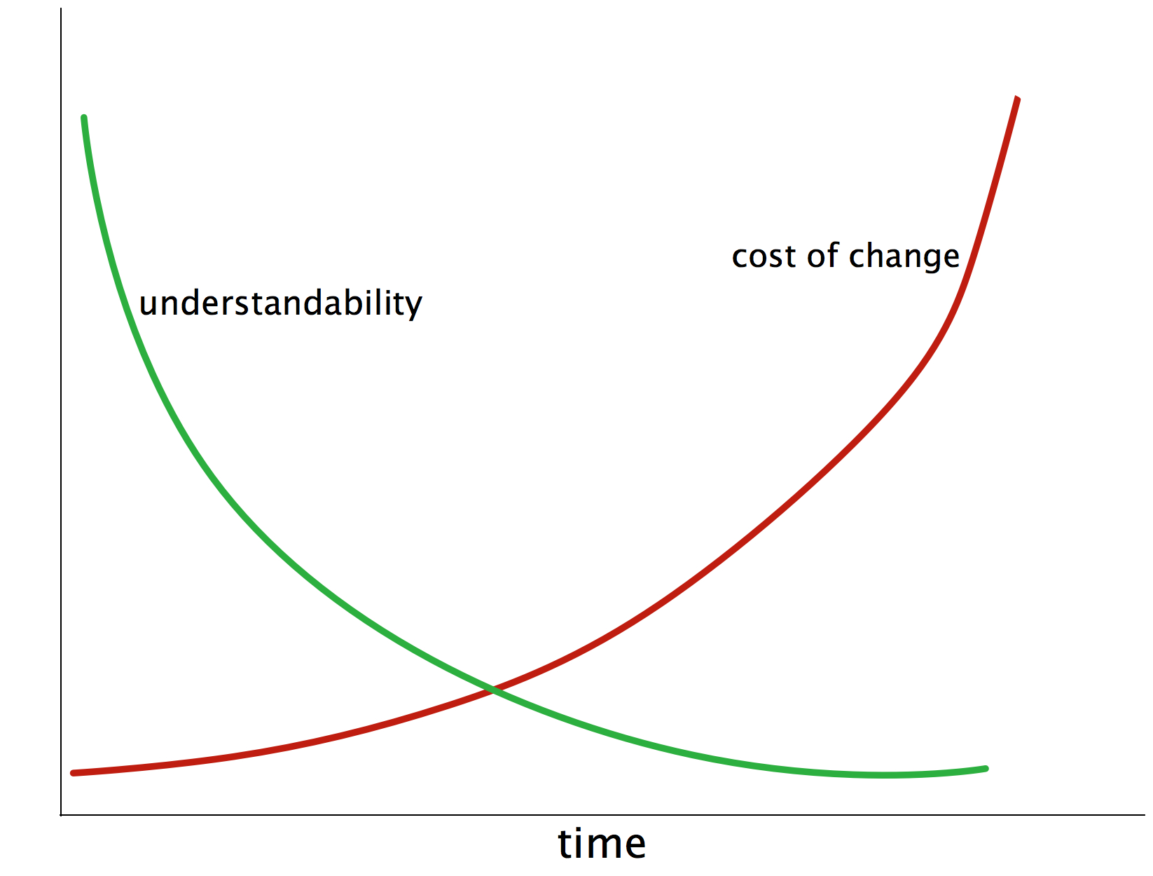
The most important reason is depicted in the following diagram: The cost-of-change of most software increases heavily over time… making those people really unhappy that have to pay for these changes (called maintenance, evolution, new-features or else).
An additional effect of long-term maintenance of software is the strong decrease in understandability: When a system matures it becomes more and more difficult to understand its inner workings, changes become increasingly risky and consequences of changes become difficult to foresee which can lead to quite blurry effort estimations.
These negative effects share a few common root causes:
-
lack of conceptual integrity
-
internal disorder
-
overly complex internal structure, either of source code or data
-
overly complex concepts (cross-cutting solutions for fine-grained problems)
-
overly complex or inappropriate internal processes
-
inappropriate selection of technology (frameworks, libraries or languages)
-
(you surely can find a few more…)
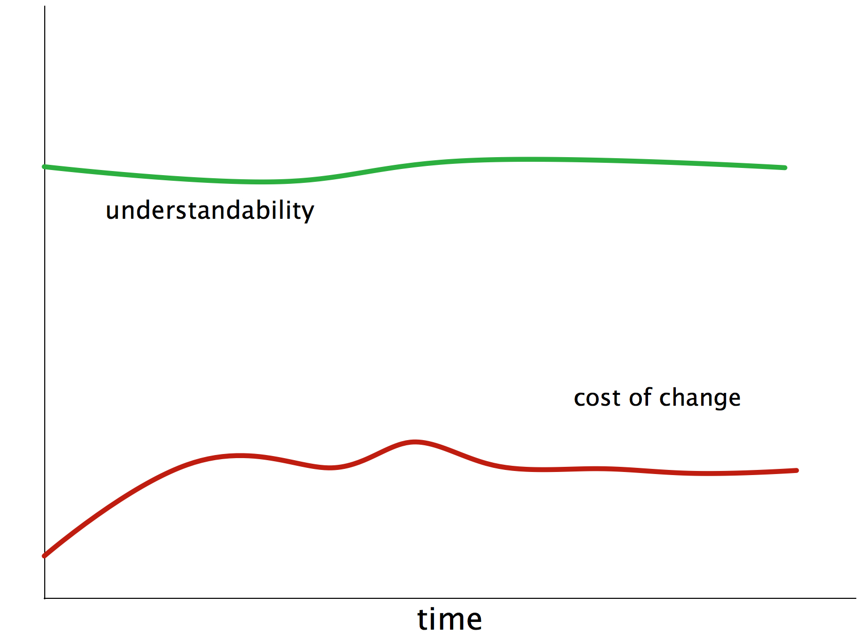
1.3.1. Long-term Goal
In the beginning, though, everything was fine: nice coupling and cohesion, appropriate technologies, well written code, understandable structures and concepts (see figure Figure 3, “Goal: Maintainable Software”)
But as more and more changes, modifications, tweaks and supposed optimizations were performed under growing time and budget pressure, things got nasty. The maintainers piled up so called technical debt (we software folks call it quick-hacks, quick-and-dirty-fixes, detours or abbreviations). We’re quite sure you know what we’re talking about - we experienced it over and over again, it seems to be the normal situation, not the (bad) exception.
Investment in methodical and systematic software architecture improvement will have the following effect.
1.4. How does aim42 work?
1.4.1. Three Simple Phases
aim42 works in a phased iterative manner:
-
Chapter 2, Analyze: collect issues: problems, risks, deficiencies and technical debt within your system and your development process. Focus on problems in this phase, not on potential solution approaches. In addition, develop (and document) an understanding of internal structures, concepts and architectural approaches.
-
Chapter 3, Evaluate: determine the "value" of issues and their solutions (improvements)
-
Chapter 4, Improve: systematically improve code and structures, reduce technical debt, remove waste and optimize.
These three phases are performed iteratively - as explained below. Several cross-cutting practices and patterns should be applied in all phases, for example documenting results, Section 5.6, “Collect Opportunities for Improvement” or long- and short-term planning activities.
1.4.2. Common Terminology
aim42 relies on a common terminology, a small set of fundamental concepts.
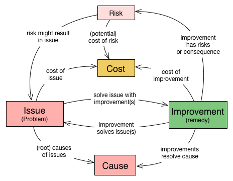
Issue |
Any problem, error, fault, risk, suboptimal situation or their causes within the [System] or processes related to it (e.g. management, operational, development, administrative or organizational activities). |
Cause |
Fundamental reason for one or several issues. |
Improvement |
Solution, remedy or cure for one or several issues. |
Cost (of issue) |
The cost (in any unit appropriate for business, e.g. money, effort or such) of the issue, related to a frequency or period of time. For example – cost of every occurrence of the issue or recurring cost per week. |
Cost (of improvement) |
The cost (in monetary units) of the improvement, remedy, tactic or strategy. |
Risk |
Potential problem. Improvements can change associated risks for the better or the worse, even create new risks. |
See also the more detailed Appendix A, Domain Model (not required for the casual reader)
1.4.3. Iterative Approach
In compliance with modern agile development methodologies, aim42 fundamentally depends on iteration and feedback between the phases.
Within each phase, you collect both issues and opportunities for improvement, as depicted in the illustration below:
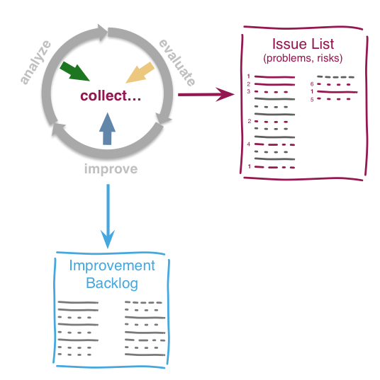
Issues and improvements need to be
-
related to each other: No idea of improvement without an existing issue - as we do not want to optimize "because we can".
-
evaluated in some business-compatible unit (e. g. Euro, $) as described above. See Chapter 3, Evaluate.
1.5. Patterns and Practices Provide No Guarantee
We are very sure that aim42 can work for your system or your organization. But (yes, there’s always a but) we cannot guarantee: Maybe your software is so extraordinary, so very special, that it needs other treatments.
Maybe your organization does not fit our prerequisites or is way more advanced than we anticipated in our approach…
You have to use all practices, patterns and approaches of aim42 at your own risk and responsibility. We (the aim42 contributor team) can by no means be held responsible for any results of applying aim42.
2. Analyze
2.1. Goals
-
Obtain overview of intent, purpose and quality requirements of the system ([System]).
-
Develop and document an understanding of internal structures, concepts and architectural approaches.
-
Find all problems, issues, symptoms, risks or technical debt within the system ([System]), its operation, maintenance or otherwise related processes.
-
Understand root causes of the problems found, potential interdependencies between issues.
2.2. How it works
Look systematically for such issues at various places and with support of various people.
| To effectively find issues, you need an appropriate amount of understanding of the system under design ([System]), its technical concepts, code structure, inner workings, major external interfaces and its development process. |
One serious risk in this phase is a premature restriction to certain artifacts or aspects of the system: If you search with a microscope, you’re likely to miss several aspects.
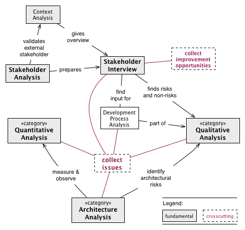
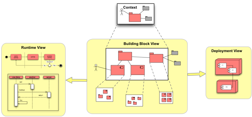
Figure: Overview of Most Important Analysis Practices
Always begin with Section 2.3.23, “Stakeholder Analysis”, then conduct Section 2.3.24, “Stakeholder Interview” with important stakeholders.
Improve your Section 5.5, “Architectural-Understanding” of the [System] by
-
Section 2.3.7, “Documentation-Analysis”, read especially the architecture documentation, focus on Section 2.3.28, “View Based Understanding”.
-
Perform Section 2.3.25, “Static Code Analysis” to learn about code structure in-the-large. This also helps to identify risky code.
-
Section 2.3.2, “Capture Quality Requirements” from the authoritative stakeholders of the systems.
-
Conduct a Section 2.3.14, “Qualitative Analysis” of the system, its architecture and associated organization, based upon the specific quality requirements
-
-
Inspect and analyze all involved organizational processes - (development, project management, operations, requirements analysis)
-
Perform Section 2.3.21, “Runtime-Analysis” or Section 2.3.15, “Quantitative-Analysis”, e.g. performance and load monitoring, process and thread analysis
-
-
Inspect the data created, modified and queried by the system for structure, size, volume or specialities
Finally, conduct a Section 2.3.20, “Root Cause Analysis” for the discovered major issues in close collaboration with the appropriate stakeholders.
| Never start solving problems until you have a thorough understanding of the current stakeholder requirements. Otherwise you’ll risk wasting effort in areas which no influential stakeholder cares about. |
2.3. Patterns and Practices for Analysis
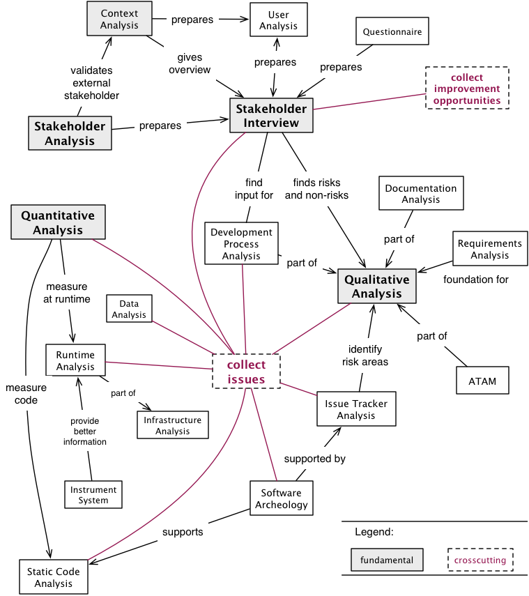
Figure: Detailed overview of Analysis Practices and Patterns
2.3.1. Atam
Architecture Tradeoff Analysis Method. Systematic approach to find architectural risks, tradeoffs and sensitivity points.
Intent
Apply the ATAM method to evaluate the software architecture regarding the compliance with quality goals.
Description
The ATAM method consists of four phases as shown in diagram "Approach of ATAM".
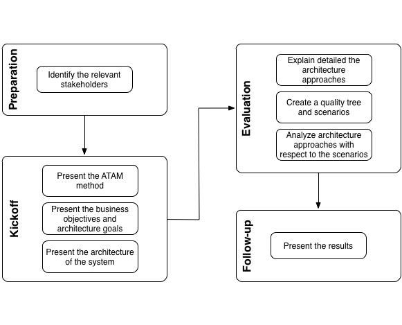
The phases are:
-
Preparation:
-
Identify the relevant stakeholders: The specific goals of the relevant stakeholders define the primary goals of the architecture. Who belongs to these relevant stakeholders has to be determined by a Section 2.3.23, “Stakeholder Analysis”.
-
-
Kickoff:
-
Present the ATAM method: Convince the relevant stakeholders of the significance of comprehensible and specific architecture and quality goals. ATAM helps identify risks, non-risks, tradeoffs and sensitivity points. Calculation of quantitative attributes is not subject of this method.
-
Present the business objectives and architecture goals: Present the business context to the relevant stakeholders, especially the business motivation and reasons for the development of the system. Clarify specific requirements that the architecture should meet, for instance flexibility, modifiability and performance.
-
Present the architecture of the system: The architect presents the architecture of the system. This includes:
-
All other systems with interactions to the [System],
-
building blocks of the top abstraction level,
-
runtime views of some important use cases,
-
change or modification scenarios.
-
-
-
Evaluation:
-
Explain in detail the architecture approaches: The following questions are answered by the architect or developers:
-
How are the relevant quality requirements achieved within the architecture or the implementation?
-
What are the structures and concepts solving the relevant problems or challenges?
-
What are the important design decisions of the architecture?
-
-
Create a quality tree and scenarios: In the context of a creative brainstorming the stakeholders develop the relevant required quality goals. These are arranged in a quality tree. Afterward the quality requirements and architecture goals of the system are refined by scenarios which are added to the quality tree. The found scenarios are prioritized regarding to their business value.
-
Analyze the architecture approaches with respect to the scenarios: Based on the priorities of the scenarios the evaluation team examines together with the architect or developers how the architecture approaches support the considered scenario. The findings of the analysis are:
-
Existing risks concerning the attainment of the architecture goals.
-
Non-risks which means that the quality requirements are achieved.
-
Tradeoff points which are decisions that affect the quality attributes positive and other negative.
-
Sensitivity points which are elements of the architecture that have formative influence to the quality attributes.
-
-
-
Follow-up:
-
Present the results: Creation of a report with:
-
Architectural approaches
-
Quality tree with prioritized scenarios
-
Risks
-
Non-risks
-
Tradeoffs
-
Sensitivity points
-
-
Experiences
The ATAM method:
-
provides operational, specific quality requirements,
-
discloses important architectural decisions of the [System],
-
promotes the communication between relevant stakeholders.
| The ATAM method does not develop concrete measures, strategies or tactics against the found risks. |
ATAM has been successfully applied by many organizations to a variety of systems. It is widely regarded as the most important systematic approach to qualitative system/architecture analysis [1].
2.3.2. Capture Quality Requirements
Description
Invite authoritative stakeholders to a joint workshop (e.g. half- or full-day). Let them write quality scenarios to describe their specific quality requirements for the system. Moderate this workshop.
-
Use scenarios to formulate specific quality requirements.
-
Order those scenarios within a mostly hierarchical quality tree, similar to [ISO-9126].
Scenario-based Quality Description
- Scenario
-
describes the reaction of a system to a certain event (or type of event).
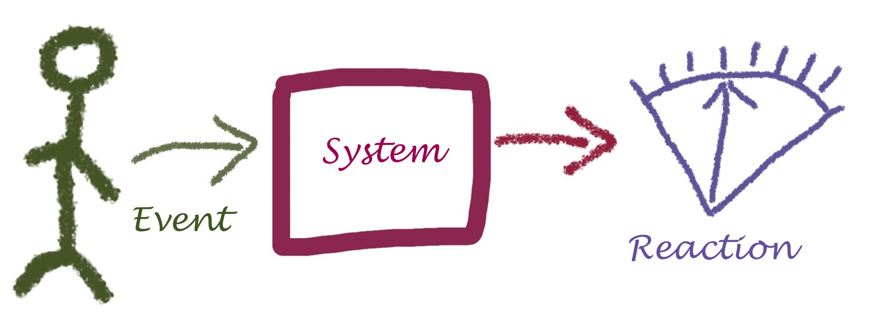
Although this definition is concise, it needs some explanation to become understandable. See figure Figure 9, “Structure of Quality Scenarios”:
-
An event can be
-
a user clicking a button
-
an administrator starting or stopping the system
-
a hacker trying to get unauthorized access.
-
-
An event can also be
-
a manager needing another feature
-
another manager wanting to reduce operation costs
-
some government agency requiring financial data to be tamper-proof
-
Context |
The individual processing step AB within use case XY is declared invalid by the regulatory authority and removed from the system. The data processed by the system is not affected. |
Business Goal(s) |
The needed changes to the use case XY can be carried out at low cost and without negative effects. |
Trigger |
The legislator, represented by the regulatory authority, prohibits the use of the AB processing step. |
Reaction |
A developer or architect removes the AB processing step in the system (by deleting the corresponding calls or reconfiguring the process flows). |
Target value |
The change requires a maximum of 24 hours with a maximum of 48 person-hours of effort. After this time, the system is fully working again. |
Constraints |
This change has no effect on the existing data of the users/customers in the system regarding the XY application case. An (automatic) migration of some data is permitted, but must not exceed the 24-hour limit. |
Such a scenario makes it clear to everyone that not only business functionality is needed to achieve the project’s goals. It makes technical requirements (in the example above: modifiability) visible to non-technical stakeholders by providing traceability from the business goal to the technical details.
Experiences
-
Needs moderation: Brainstorming quality requirements usually works well in moderated workshops. If given (even trivial) examples, every stakeholder will most likely write down several scenarios. We often received 80-120 different scenarios in one-day workshops.
-
Uncovers problems and risks: Scenarios collected within brainstorming sessions often contain hidden problem descriptions, risks or problems with the current systems.
-
Covers organization and process: Scenarios sometimes cover process or organizational aspects (like release cycles should be faster than they are now). Move those to your Section 5.14, “Improvement Backlog”.
-
Improves human communication: Different stakeholders often start communicating about the system or their requirements during such workshops. This kind of interaction should have happened long before…
Applicability
Use this practice when (authoritative) stakeholders are available for discussion or a workshop.
If you have well-documented, specific and current (!) quality requirements available, you might consider skipping this practice for now (although we’re quite sure it’s a good opportunity to learn a lot about the system, its stakeholders, their requirements and opinions).
Also Known As
-
Non-functional requirements (although this term is misleading, as functional requirements strongly influence the quality of any system!)
-
Documentation of quality requirements.
References
The workshop-based collection of quality requirements has been described by [Clements-ATAM].
-
Real-world examples of software quality requirements (currently available only in German): https://github.com/arc42/quality-requirements
-
[Clements-ATAM] contains a brief description of scenario-based quality description and details on how to set up such workshops.
2.3.3. Context-Analysis
Intent
-
Analyse external interfaces for risk, technology, business value and other factors.
-
Use the context to gain overview of the System within its business or technical environment.
-
Identify risks or problems in the immediate vicinity of the System.
Terminology
We distinguish the following terms in context analysis:
- Business Context
-
Adjacent organizations, applications, users or interfaces either requiring or providing services or data from or to the System. The business context can be used to describe the overall business process(es) the System is involved in.
- Technical Context
-
Adjacent hardware or technical infrastructure, either required by the System or providing data or events to it. When the System can be used or operated in different hardware infrastructures, there might exist several different technical contexts.
Description
Context analysis shall help identify issues associated with external interfaces, e.g. interfaces that:
-
influence critical quality requirements of the system (e.g. reliability, security, throughput, runtime performance, operation cost)
-
are overly complex
-
are brittle or fragile
-
are implemented with unsuitable technology
-
are underdocumented or poorly understood
-
transport critical data (important, sensitive, insecure)
-
transport especially huge amounts of data
-
have high operational effort
-
have high usage cost (e.g. cost-per-request or similar)
-
have high cost-of-change or high maintenance costs
-
are difficult or impossible to modify/enhance/change
-
suffer from operational failures or production issues
Note that user interfaces often belong to the context, especially with respect to the kind of data or events exchanged with users or user groups. Due to the importance of this topic, aim42 devotes an own section to it.
Example
In the context diagram example of fig. Figure 10, “Example of Context View” you see some user roles and some external systems. The context diagram is accompanied by a tabular description of the elements and/or relationships. Example taken from the HtmlSanityCheck (HtmlSC) open source project.
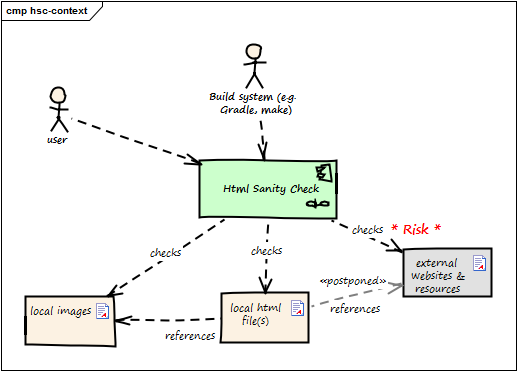
| Neighbor | Description |
|---|---|
user |
documents software with toolchain that generates HTML. Wants to ensure that links within this HTML are valid. |
build system |
|
local HTML files |
HtmlSC reads and parses local HTML files and performs sanity checks within those. |
local image files |
HtmlSC checks if linked images exist as (local) files. |
external web resources |
HtmlSC can be configured to optionally check for the existence of external web resources. Due to the nature of web systems, this check might need a significant amount of time and might yield invalid results due to network and latency issues. |
In this example, the complete check has to be completed within 5 seconds (a quality requirement). As access to external websites or resources might be hindered by network latency or even failures, the external interface responsible for this requirement will likely contain risks.
2.3.4. Data-Analysis
Intent
Analyze and inspect the data created and manipulated by the system for its content, structure, quantity and size.
Description
In data analysis you could examine the following topics:
-
Data Actuality and Correctness (which covers integrity issues as well)
-
Analyze Data Distribution, Replication and Syncing
Analyze Data Structures
Are data structures suited to represent the problem domain?
At first, make the structure of the existing data explicit, e.g. by creating a rough sketch of a data model as either informal diagrams, entity-relationship or class diagrams. Focus should be on overview: Where and how are which kinds of data stored in which format. What are the relationships between the data elements?
Second, create an explicit model of the required domain data structures.
Some typical questions might help in finding problems:
-
structural differences between those two models?
-
differences in data types?
-
differences in plausibility or validity checking?
Analyze Data Access
Get an overview of data access paths: How is data read or written? Do the queries match their requirements, or are complex mappings or unsuitable indirections involved?
-
What queries or executed how often?
-
How large are the results in number or volume?
-
Do relationships between query results have to be computed or do appropriate indices exist?
Analyze Data Size
-
Are some parts of the data especially large?
-
Is the relation between record-size (how large is a single record?) and record-volume (how many records exists?) plausible?
-
Do critical queries involve especially large parts of data?
Analyze Data Validation
-
How is data validated? (upon write, upon read, on client, on server, redundantly, uniformly)
-
Is validation consistent with current business rules?
-
Is validation overly complex?
-
Is validation implemented with appropriate technical means?
Analyze Data Actuality and Correctness
Especially in data concerning dynamic entities like people, organizations, markets, commodities etc., facts are very likely to change over time. Such data (stored facts) might become invalid sooner or later. Other types of information (like tax records, invoices or bookings on bank accounts) are created once and remain valid forever).
|
-
Which parts of the data are subject to (what kind of) changes?
-
Are parts of the data known to be invalid or contain invalid portions?
-
Does the System handle potentially wrong or invalid data appropriately?
-
Are there (organizational or technical) processes in place that deal with data inconsistencies or faults?
Analyze Data Access Protection
-
Is there an overview what kinds of data need which level of (access) protection?
-
Is there a security concept in place covering protection against unauthorized access?
-
How are users/roles/organizations allowed to access data managed?
-
Is there a process in place to revoke access for outdated users/roles/organizations?
-
-
Is there a plan what shall happen in case of security breaches or data theft?
-
How is data theft recognized?
2.3.5. Debugging
Intent
Identify the source of an error (bug) or misbehavior by observing the flow of execution of a program in detail.
| Many software developers we met violated the basic rules of debugging. They worked in haste, took wrong assumptions, imagined-instead-of-read or simply hunted bugs at the wrong parts of the system. |
Description
Debuggers are well-known and important tools for most software developers. Yet finding bugs is often more difficult than expected - despite powerful tool support.
Approach the search for bugs, errors in the following order:
-
Get a clear and precise description of the error, the detailed wording of all error messages, log messages, stacktraces or similar information.
-
Know the context of the error: the exact version of the system, the operating system, involved middleware, hardware settings and so on. Have knowledge of the input data which leads to the error.
-
Minimize external disturbance while searching for errors, you need to concentrate and observe details. Shut off chat and twitter clients, notifications and your phone. Send away your boss to an important management mission and lean back to reflect the error. Perhaps a colleague can support you.
-
Reproduce the error in the live system. Don’t rely on the assumption you can reproduce it - make sure you can reliably really reproduce it.
-
Obtain the exact version of all required source code and all involved data.
-
Reproduce the error in development environment: This ensures your development environment is consistent to the live system.
-
Rephrase your error assumption into a question: Distinguish symptoms from the cause of the error by asking "why?" a few times.
-
Identify the building blocks which are involved in the error path.
-
Understand the error scenario: You need to know the business or technical scenario (aka the process or activity flow) of the error: Which steps within the system or its external interfaces precede the error? This step is an example of Section 2.3.28, “View Based Understanding”.
-
Make this scenario explicit - draw or scribble a diagram. See the diagram "Divide and conquer" below as an example. Here the error arises in building block 1. You suppose the processing within the system is spanned by the blue marked data path in which the building blocks 2 to 6 are involved. Cut the path in half and check your assumption at the transition of one half to the other (here between building block 4 and 3). If no error is observable here then the error occurs after the considered transition. Otherwise you have to look for the error before the transition.
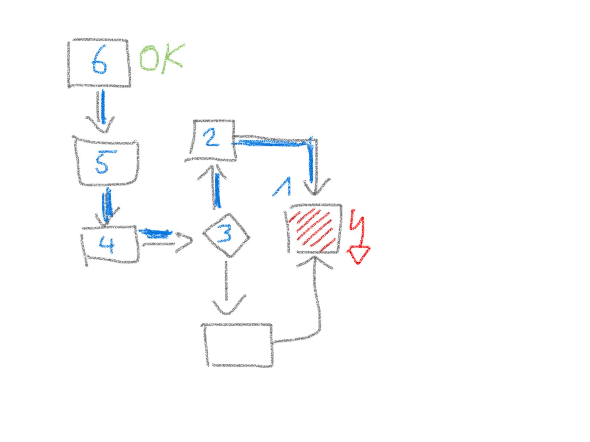 Figure 11. Divide and conquer debugging tactics
 -
Plan your debugging strategy: Think of the expected outcome of every part of your scenario.
-
If you know you’re traveling to Pisa (Italy), you won’t confuse the Leaning Tower with an error.
-
-
Look, don’t imagine: Sherlock Holmes, the successful detective has formulated the golden rule of debugging: "It’s a capital mistake to theorize before one has data". Instrument the system or use step debugging. Look exactly what the messages are, read carefully.
-
Change only one thing at a time and test if the error disappears: Aim for errors with a sniper rifle, not with a shotgun.
-
Apply the 4-Eye-Principle: Describe the problem and your state of debugging to somebody else. Especially clarify all your assumptions.
Experiences
If locating errors takes very long, you’re probably facing one of the following issues:
-
You suffer from any assumption that’s currently not valid.
-
You think something instead of observing it - you let your mind deceive your eyes or ears.
-
You ignore the context: you test a wrong version, with wrong data or a wrong operating system.
Applicability
-
Whenever a bug or misbehavior of a program is reported, debugging can help to identify its root cause.
-
Debugging can help to understand a system by making its inner working explicit.
2.3.6. Development-Process-Analysis
2.3.7. Documentation-Analysis
2.3.8. Infrastructure-Analysis
Intent
Analyze the technical infrastructure of the [System], e.g. with respect to time and resource consumption or creation. Part of Section 2.3.21, “Runtime-Analysis”.
Description
Infrastructure analysis is associated to the more general Section 2.3.21, “Runtime-Analysis”, with focus on technical infrastructure for operation, test and development of the [System].
Inspect and analyse the technical infrastructure, for example the following aspects:
-
production hardware: does characteristics, type and size of the hardware suit the system and the business problem? Hardware might consist of several subsystems, like processing, various levels of storage (processor cache, RAM, flash, disk, tape or others), graphical and network interfaces and arbitrary specialized hardware
-
development and test hardware
-
software infrastructure, like operating system, required database, middleware, frameworks and libraries
It helps to measure runtime behavior agains expected or required values, for example processing time and memory consumption. Section 2.3.10, “Instrument System” can support this type of analysis.
Specialized stakeholders (like datacenter administrators, operating-system or database experts, hardware designers) can often pinpoint critical aspects of existing infrastructures from their experience.
Apply Section 2.3.28, “View Based Understanding”, especially an infrastructure overview (e.g. deployment diagram) to get an overview of existing hardware plus the associated software. Start with an hardware context and refine. Ensure you have at least all hardware-types (node-types) plus their relations (networks, buses) visible. Double-check this overview with the appropriate stakeholders.
2.3.9. Hierarchical-Quality-Model
Intent
Decompose the overall goal of "high quality" into more detailed and precise requirements, finally resulting in a tree-like structure. See Section 2.3.1, “Atam” and [Quality-Requirements].
2.3.10. Instrument System
Use retroactive modification of the executables which target cross-cutting concerns to make the existing software-base tell about it’s internals. Ways to achieve this can include aspect-oriented programming (AOP), Monkey-Patching and other metaprogramming techniques.
Intent
Find out how the system is really used and what the runtime relationships are, as well as other facts that can not be easily determined by Section 2.3.25, “Static Code Analysis” even in situation where the system under design is largely undocumented and the architecture work thus mostly relies on assumptions, interviews and lore.
Description
In many languages today it is possible to define operation that alter the behavior of certain structures in the system without modifying the original source code. In Java this is often done by byte code instrumentation, in Ruby, PHP and some other languages there are built in mechanisms to (re-) define the behavior of system classes or libraries.
In theory instrumenting the system therefore is a straightforward process:
-
Identify and describe the concern that shall be explored (e.g. object creation, function entries and exits, code execution or something else that can be described in the terms of the mechanism used).
-
Write the code that collects the data about the system behavior (e.g. sends it to a syslog, writes it to a file, sends it to a dedicated server, creates an SNMP Trap etc.)
-
Use the (language specific) mechanism to create the instrumented version of the system
-
Replace (part of) the currently operational system with the instrumented version
-
Collect the data
-
Replace the instrumented version with the previously operational version
In real life, since the mechanisms of instrumentation varies widely, specific ways must be found for each scenario.
While tools like AspectJ provide easy ways to instrument Java code and Ruby’s metaprogramming model allows for easy introduction of cross-cutting functionality the same gets harder to do with other languages. In some languages it may be necessary to modify a dynamically linked library with central operations to introduce instrumentation without modifying the original system.
|
A special form of this pattern, especially useful for interpreted languages, is instrumenting the source code manually. Basically all you do here is manually type in the code to collect the information you’re interested in. In this case it is especially important to have a tried and tested way to replace the instrumented system back with the original system! |
Experiences
| even if used cautiously, the instrumentation of the system under design can entail heavy performance penalties (on execution time, space used, bandwith etc.) so always make sure that there is a quick way to switch back to the original non-instrumented version. |
2.3.12. Organizational-Analysis
Description
Work-in-progress: collecting ideas and currently doing research, therefore still chaotic document
Software Organizations and their Effect on Systems
As Nagappan et al write: From the historical perspective, Fred Brooks in his classic book "The Mythical Man Month" provides an analogy in the chapter on "Why did the (mythical) Tower of Babel Fail?" The observation being that, the people had (1) a clear mission; (2) manpower; (3) (raw) materials; (4) time and (5) technology. The project failed because of communication, and its consequent organization. Brooks further states that in software systems schedule disasters, functional misfits and system bugs arise from a lack of communication between different teams. Quoting Brooks “The purpose of organization is to reduce the amount of communication and coordination necessary; hence organization is a radical attack on the communication problems…”. What many organization like Amazon, SoundCloud, Otto or Google do these days is to create self-contained, cross-functional teams with a high cohesion inside the team and loose coupling between the teams.
Cohesion in programming refers to the degree to which the elements of a component belong together, all the related code should be close to each other. For teams the same is true: all people with the necessary skills to create a feature should be close together.
Coupling in programming refers to the degree to which the different components depend on each other. Preferably, components should be independent from each other as much as possible. For teams the same should be true, different teams should communicate as little as possible. Adrian Cockcroft said regarding the independence between service teams that "You don’t go and have a deep discussion with the Google Maps team just to use their Maps API: it’s a reasonably stable API, you are isolated, it’s sort of versioned, occasionally it changes and you may want to do things. So basically you build your own service, you build a bounded context around the thing that your team, your 2 or 3 engineers, are building and you build a service or a group of services that interface with all the other things that your company is doing, as if they were separate companies. It’s a different bounded context. So you talk to them but you are not tightly coupled".
How can an organization be loosely or tightly coupled? What are those properties? MacCormack et al. answered this question in a Harvard Business School publication:
Table: Characterizing Different Organizational Forms
| Tightly-Coupled | Loosely-Coupled | |
|---|---|---|
Goals |
Shared, Explicit |
Diverse, Implicit |
Membership |
Closed, Contracted |
Open, Voluntary |
Authority |
Formal, Hierarchy |
Informal, Meritocracy |
Location |
Centralized, Collocated |
Decentralized, Distributed |
Behavior |
Planned, Coordinated |
Emergent, Independent |
Of course this is not black and white, there’s always some place in between.
Conway’s Law and what to do about it
In 1968 Conway observed that "organizations produce designs which are copies of the communication structures of these organizations (If you have four groups working on a compiler, you’ll get a 4-pass compiler)". Around 2006 many companies had a frontend, backend and middleware department reflecting the three-tier architecture they were building. Modern companies have individual deployable services built by cross-functional teams.
James Coplien wrote in his book that "If the parts of an organization (e.g. teams, departments, or subdivisions) do not closely reflect the essential parts of the product, or if the relationship between organizations do not reflect the relationships between product parts, then the project will be in trouble… Therefore: Make sure the organization is compatible with the product architecture".
David Parnas (1972, 1978) argued that it is easier to split development work across a group if people can work independently and in parallel. To support parallelism, Parnas encouraged developers to avoid sharing assumptions and data. Specifically, he contended that every developer’s task assignment should lie within a product module that is “characterized by its knowledge of a design decision that it hides from all others” (1972: p. 1056)
That means that the flexibility of an organization is important to effective design and operations. It also means that you first create your architecture and then form the organizational communication around it. This is not as crazy as it sounds, because existing departments can still exist, but the people inside those departments need to be insourced into the newly formed product teams representing end-to-end the individual services or components of the system.
If you want to improve your architecture you need to improve your organization as well
TODO: collect more examples of org transformation
Since systems usually live longer than corporate structures, it is important that managers keep their organisation flexible. An example for organizational flexibility is Soundcloud. They experimented with different organizational models to find the one that fit product development best. That experimentation is possible is important to note - many organizations don’t do that. They moved over a couple of years from the classical approach of separate development and operation teams to a structure where teams can act autonomously and build and run their systems without handovers to other teams. Since there is still a need for centralized work they created a production engineering team which takes care of common infrastructure ("run the system that runs systems") and do internal consulting in case a team needs help. For some companies experimentation is really hard, e.g., a large insurance company has 800 people in an operations department and claims because of that "You build it, you run it" is not possible, the company could still keep the departments, but in fact it practices insourcing operations people (or UX specialists or business analysts, etc.) into the product teams. That way the departments, which are hard to change, still exist, but there’s still a good chance to create a cohesive team structure.
An example of a popular change of software producing organizations is the move from operations/development/business/testing silos to functional silos (e.g. a cross functional team responsible for product search), because the optimized process-based organization is horizontally focused on outcomes, not vertically oriented around skills like testing, development and operations.
TODO: provide more case studies, e.g. UK Government Digital Services, Google, Amazon, ING, Otto
Organizational Structure and its Effect on Quality
Microsoft did a large study on how organizational structure affects software quality. The effect of organizational structure on quality is higher than code churn, code complexity, code coverage or bugs found before releasing the software. Microsoft looked at a few organisational metrics:
-
Number of Engineers (NOE): The more people who touch the code the lower the quality. This is of course something you need to balance. Of course if there is only one person who works on a component, the likelihood of conceptual integrity and few bugs is high (if the persons work quality is also good). If 300 people change the component it is much harder to keep conceptual integrity. However, a company doesn’t want knowledge islands, depending on the knowledge of one single person, therefore the company should find the right balance here. Netflix recommends 2-3 people per component, Amazon has the "Two pizza team" rule (only so many people should work on a component or service who can be fed by two pizzas)
-
Number of Ex-Engineers (NOEE): A large loss of team members affects the knowledge retention and thus quality. A similar study at eBay found out that a resource pool (a pool of developers where projects can take people out) led to very bad quality
-
Edit Frequency (EF): The more source code edits to components the higher the instability and lower the quality (sure, if I never touch code which works I won’t introduce new bugs. But we know that we need to test (heavily) changed source code with a greater intensity than less changed parts of the code)
-
Depth of Master Ownership (DMO): The lower the level of ownership the better the quality. What they mean with that is that a component should have only one clear owner and that owner (can be a team) needs to report to only one leader and not many.
-
Percentage of Org contributing to development (PO): The more cohesive the contributors organizationally the higher the quality. Means that it is important to create a team where its members share a common culture, focus and social cohesion.
-
Level of Organizational Code Ownership (OCO): The more cohesive the contributors (edits) the higher is the quality. Means that it is important to create a team where its members share a common culture on how to write and design a system.
-
Overall Organization Ownership (OOW): People who change often the same source code should sit together closely or at least know each other well and have an unproblematic way to communicate. E.g. working on a particular piece of source code with a person in another timezone lowers quality, pair programming leads to higher quality.
-
Organization Intersection Factor (OIF): The more diffused the different organizations contributing code, the lower the quality. If totally unrelated teams contribute to the source code of a component and those changes are small (< 10% of all changed lines) your quality declines. Try to not have too many contributors who only contribute little.
Statistical existence and empirical evidence stemming from organizations research and social-network analysis reveals that low organisational quality connected to software can be found in the relationships across the following combinations (combined org metrics appear in brackets): TODO: still a bit unclear
-
Low quality: Code is often changed AND the number of developers changing that code is high (EF ↔ NOE)
-
Low quality: Code is often changed AND the number of developers who changed that code left the team/organization is high (EF↔ NOEE)
-
High quality: The team is cohesive and shares a common culture/focus/social cohesion AND they own their code completely and make their own decisions (OCO ↔ DMO)
-
High quality: The team shares a common culture/focus/social cohesion AND shares a common coding culture (OCO ↔ PO)
-
High quality: The team sits together (or low distance or can easily interact) AND shares a common coding culture (OOW ↔ PO)
-
High quality: The team sits together (or low distance or can easily interact) AND they share a common culture/focus/social cohesion (OOW ↔ OCO)
Value Stream Mapping
Value stream mapping is a lean-management method for analyzing the current state of events that take a product or service from its beginning through to the customer. Examples in the software world would be all the steps needed from having an idea to implementing and deploying it (which usually requires a business case, putting it on a roadmap, write requirements, create UX prototypes, implementation, test in between).
Two key metrics associated with value stream mapping are value adding times and non value adding times (=waste). If something does not directly add value as perceived by the customer, it is waste. If there is a way to do without it, it is waste. Mary Poppendieck describes seven types of waste in software development: waiting, partially done work, extra process, extra features, task switching, defects and motion.
Often, the value stream is broken in a few places where small changes can bring large improvements. Those are the places you need to find and where you can improve the architecture. A great example how value stream mapping led to a large architectural improvement is Soundcloud’s move from monolith to Microservices and from low cohesion and strong coupling of Departments to high cohesion and loose coupling of Departments (http://philcalcado.com/2015/09/08/how_we_ended_up_with_microservices.html).
How to do a / examples of value stream mapping: TODO
Old stuff - Look for:
-
violations of Conways' law
-
over or under-regulated processes
-
organization with overly strict constraints
-
organizations lacking constraints (anarchy)
-
orga-problems leading to IT problems
2.3.13. Social Debt
Social debt amounts to additional project cost connected to sub-optimal organisational and socio-technical decisions
Intent
Evaluate and track the welfare and health of a software development and operation organization or community such that additional project cost can be avoided or somehow managed.
Description
Organization, coordination and cooperation are critical forces behind software development and operation. Through well-thought protocols and cooperation guidelines, software architects, developers as much as entire organizations try to orchestrate proper coordination and cooperation but many times such attempts are burdened by sub-optimal organisational decisions, e.g., the adoption of a process model that is not compatible with developers and operators’ background and mindset or even collaborating with an organization that does not and cannot share the same values of the organization in question. These circumstances often result in additional project cost in the form of recurrent delays, condescending behaviour or worse.
Evaluating these circumstances together, trying to minimise their impact on software development and the quality of resulting software products is currently object of intensive study.
The goal for social debt in the next few years of research is that of reaching a crisp definition that contains the essential traits of social debt which can be refined into practical operationalizations for use by software engineering professionals in need of knowing more about their organizational structure and the properties/cost trade-off that structure currently reflects.
Experiences
As previously mentioned, we found three recurrent series of circumstances in which architecture decisions and the process of architecting reportedly generated social debt.
-
Lonesome Architecting: we observed this pattern manifesting when non-architects are forced to make decisions while actual architects are "too few and far apart". One of the software architects reporting this condition in industry also complained that he and his colleagues had […] not enough time to dedicate to decision-making (and related changes) as well as properly disseminating architecture decisions. Some of the most common consequences we found resulting from this pattern are: (a) decision unawareness; (b) misalignment between product version and architecture; (c) lack of awareness on the product’s needs; (d) overly fast decision-making to "patch-up". The debt in this case is associated to delays needed to find out about decisions and apply the necessary modifications, possibly rewriting code with considerable waste. Also, from a social point of view, this circumstance results in loss of project vision (i.e., frequent quotes were "what are we doing? what does the product need for its improvement?") with resulting frustration and mistrust.
-
Obfuscated Architecting: Obfuscated architecting takes place when multiple sub-groups emerge in a development network without a harmonised organisational and socio-technical vision necessary to operate in the network. We observed this pattern manifesting when new or changed architecture decisions imply implementation changes that necessitate new people to be included in the development network (e.g., different skills are needed). we observed this pattern in presence of multiple products (both legacy and new) being operated together but in the process of being integrated. New people to be included in the development network lacked the frame of mind and vision needed to understand and cope with the legacy product. This obfuscates the communication of architecture decisions. Some of the most common consequences we found resulting from this pattern are: (a) single communication points for architecture decisions - many developers eventually felt left out of the development network when it came to software architecture, since they could not reach architects properly, this led to time waste and resulting developers' frustration; (b) circumstances indicating socio-technical code-churn.
-
Architecting by Osmosis: In layman’s terms, osmosis refers to the process of permeating a solvent through a semi-permeable (series of) membrane(s). By comparison, architecting by osmosis means making architecture decisions using knowledge that is filtered through many semi-permeable communication links. we observed architecting by osmosis manifesting when the following sequence of events occurs: (1) the effects of certain decisions reach clients and product operators but result in inoperable software; (2) operators, pushed by clients, share malcontent with developers and suggest technical changes; (3) developers evaluate (and sometimes partially implement) possible technical changes and suggest change to architecture decisions; (4) architects make necessary changes in decisions with knowledge that was partially filtered by all communication layers in the development network.
References
-
Damian Tamburri, Philippe Kruchten, Patricia Lago, Hans van Vliet: What is social debt in software engineering? In: Cooperative and Human Aspects of Software Engineering (CHASE), p. 93–96, 2013, Washington, DC. https://jisajournal.springeropen.com/articles/10.1186/s13174-015-0024-6
-
Tamburri, D. A. & Nitto, E. D. (2015), When Software Architecture Leads to Social Debt., in Len Bass; Patricia Lago & Philippe Kruchten, ed., 'WICSA' , IEEE Computer Society, , pp. 61-64 .
2.3.14. Qualitative Analysis
Intent
Find out (analyze):
-
whether quality requirements can be met by the system,
-
which specific quality requirements are risks with respect to the current architecture,
-
which specific quality requirements are currently non-risks
Description
-
Capture quality requirements to ensure you have explicit, specific, valid and current quality requirements available - preferably in form of scenarios.
-
Prioritize these scenarios with respect to business value or importance for the authoritative stakeholders.
-
For every important scenario:
-
analyze the architectural approach the system takes,
-
decide whether this approach seems appropriate or risky
-
Experiences
-
Conducting workshops with a variety of stakeholders often leads to intense and productive communication.
Applicability
Use qualitative analysis to support in the following situations:
-
You need to analyze which specific quality requirements are at risk and which will most likely be met by the system.
-
You have a variety of different stakeholders or groups which can all impose quality requiements - but have not yet agreed on a common set of such requirements.
-
A current and understandable collection of specific quality requirements for the system is missing.
References
-
Section 2.3.1, “Atam”. Published by the Software Engineering Institute in numerous whitepapers and books, especially [Clements-ATAM].
2.3.16. Pre Interview Questionnaire
Intent
Prior to interviewing stakeholders, present them with a written questionnaire, so they can reflect in advance.
Description
A specialisation of questionnaire - targeted to be used by stakeholders (aka your interview partners). As with the more general questionnaire you need to collect appropriate topics, questions and suggestions. Remember to apply stakeholder-specific communication: It might be useful to create different questionnaires per stakeholder or a group of stakeholders. This can lead to more work for you as interviewer, but will also lead to better interview results.
Mix open and closed questions:
-
open questions require stakeholders to formulate answers on their own. For example "How did you…?" or "Please explain…?"
-
closed questions ask stakeholders to select from several predefined choices.
Include a "Comments/Remarks" section at the end of the questionnaire, so stakeholders can comment on topics you did not consider in advance. The Section 2.3.16, “Pre Interview Questionnaire” shall be handed over to the appropriate stakeholders in advance, a few days before the interview. As these documents will be read and processed by external and potentially critical stakeholders, you need to care for several details:
-
Stakeholder specific terminology: Ensure your questions will be understandable by the target audience. See [Stakeholder-Specific-Communication].
-
Ensure nice layout and (visual) readability. Your questionnaire shall be fun to work with.
-
Ensure timely delivery to your stakeholders, so they have enough time to think about their answers. Do never force your stakeholders to answer questions under time pressure.
2.3.17. Pre-Mortem
Description
In software projects, post-mortems are often used to learn from a failed projects with the goal to avoid the identified problems in the future. But why wait for so long?
In a pre-mortem workshop, stakeholders are imaging that they are living some months or years in the future to analyse their current project that had been failed miserably. They are explicitly encouraged to speak about the main points that did go wrong from the future’s perspective.
The organization of the workshop for a running software project can be done as follows:
-
Preparation: Participants are gathering in a room with a big empty wall. For each participant, a pen, around ten post-its and three adhesive dot markers are handed out.
-
Scenario: The workshop facilitator tells all participant that they are now in the future and their project has failed. It failed so miserably that it was a total disaster. The project members don’t speak to each other anymore and the whole company gained a bad reputation.
-
Task: To come over this heavy shock, all former project members are summoned together to spot the reasons for this fiasco. Each of the participants should write down the concrete reasons that led the complete failure (within a 5 minutes timebox, one reason on one post-it).
-
Communication: Each participant puts their post-it notes on the wall and explains each identified reason in 1-2 short sentences.
-
Grouping: The facilitator groups the post-its together to main topics and names these main topics with additional post-its that placed onto the emerged groups.
-
Prioritization: All participants can now use the dot stickers to mark the three most important topics (no accumulation allowed) from their point of view.
-
Discussion (optional): Possible solutions that address the three most important reasons are discussed and the next steps to implement the solutions are defined.
Experiences
A pre-mortem session combines the potential of negative thinking and creative thinking in a relaxed environment. Stakeholders are rewarded for the identification of issues instead of being played down or marked as naysayers. This leads to a huge amount of input from all kind of participants that would otherwise be quite regarding potential problems. The viewpoint from the future frees participants from thinking just in short terms and provides.
Applicability
Pre-mortem is a complementary method to interviews with stakeholders, that is very efficient due to the focused scenario and multi-perspective format.
Consequences
In the evaluate phase, the identified reasons can be a great starting point for further analysis.
Additionally, identified reasons from a pre-mortem session can be seen as potential risks and thus be included and tracked in the project’s risk management.
References
-
Gary Klein - Performing a Project Premortem (Online article)
2.3.18. Questionnaire
Description
Prior to taking interviews with stakeholders, formulate questions covering the topics or areas of information that:
-
might be important for you
-
your interview partners (== the stakeholders) have knowledge or experience in.
The questionnaire can be specific for a single interview or be a template for multiple interviews.
Experiences
I (Gernot Starke) used such questionnaires within several technical reviews and audits. They helped me to stay on track, cover a multitude of topics, even when I conducted several interviews consecutively.
I usually printed out one copy of the questionnaire for every interview I had planned, so I could sketch notes - and always had the context of my notes already printed, saving a lot of note-taking effort.
Applicability
Whenever you interview stakeholders, a thorough preparation will lead to better results, interviewers will be less likely to forget important topics.
2.3.20. Root Cause Analysis
To find mistakes is not enough. It is necessary to find the cause behind the mistake and build a system that minimizes future mistakes.
Intent
Explicitly differentiate between symptom and cause:
-
Identify root causes of symptoms, problems or issues
-
Trace a problem to its origins
Description
Some people fight problems, not their real cause: When faced with a problem our brains tend to start immediately to search for proper solutions for exactly this problem. For instance, if our application regularly crashes with Out-Of-Memory-Errors it might be a reflex to increase the memory settings. Instead we should ask if this is really the problem or only a symptom of the real problem, e.g. a programming failure in memory releasing. With an iterative process of asking "Why?" the causal chain must be traced down to the root cause.
Experiences
|
Users of a system complained about low performance. Developers started tuning the database, tweaking the application server, optimizing inner loops and so on (you pretty well know what I mean). That did not solve the issue. After applying Section 2.3.26, “Take What They Mean, Not What They Say” we found out that users complained about low performance in data entry, as they had to switch back-and-forth between different regions on their input-screens. The actual cause of their complaint was the improper field order in their input forms. After adapting this order by simply dragging fields/labels around the screen, users were perfectly happy with the systems. |
Related Patterns
-
Section 2.3.26, “Take What They Mean, Not What They Say”, maybe what they told you was not the real problem.
2.3.21. Runtime-Analysis
Intent
Analyze the runtime behavior of the [System], e.g. with respect to time and resource consumption or creation.
Description
-
Ask stakeholders about perceived runtime behavior - double check by measuring.
-
Measure runtime behavior, e.g. with profilers, logs or traces.
-
Inspect artifacts created at runtime (e.g. logfiles, protocolls, system-traces) for information about problems, root-causes or system behavior.
-
Perform Section 2.3.8, “Infrastructure-Analysis” to learn about the technical infrastructure.
- WARNING
-
Measuring might influence behavior. That can be especially disturbing in multi-threaded, multi-user or multi-core applications.
2.3.22. Software Archeology
Description
-
Make sure you have the complete code, scripts, frameworks and tools required to build the system.
-
Ensure you have access rights to all required systems, at least to version control, database, participating servers etc.
-
Ensure you can build the system from scratch (compile, load all dependencies, link or whatever steps are necessary).
-
Practice View-Based Understanding by sketching notes or diagrams. Get an aerial view, a glimpse of the topmost, biggest structures in the code.
-
Try to understand the terminology of the original authors by scanning code and searching for multiple occurrences. Start creating a glossary.
-
Introduce tracing or logging statements. Aspect-oriented tools (like AspectJ) might be helpful.
Experience
-
By examining the build scripts of the software project or the job definitions on a continuous integration server, you can build the software and the needed testing environment on your own.
-
With simple tools like the
git shortlog -nscommand you can easily check parts of a software system for potential loss of knowledge based on the commits per developer. -
By using word clouds, you can quickly extract the most occurring terms in your source code and start creating a glossary for the most prominent words.
Applicability
You have to understand a system with:
-
little or no current documentation.
-
no knowledgeable technical stakeholders or development team available
References
-
[Hunt-Archeology], pleasant introduction without adherence to any strict pattern template. Recommended reading.
-
[Moyer-Archeology], short report.
-
[OORP], page 53ff. , "Read all the Code in One Hour" suggest to read all source code in a short period of time to get a rough feeling about the software system.
-
[OORP], page 97ff. , "Speculate about Design" suggest to create diagrams based on hypothesis and progressive refinement.
-
[Tornhill-XRay] shows many ways of using version control systems to recreate knowledge about software systems.
2.3.23. Stakeholder Analysis
Find out which people, roles, organizational units or organizations have interests in the [System].
Description
Get an initial list of stakeholders from project management.
Distinguish between roles and individuals. Some stakeholders need to be adressed individually, for roles it might be sufficient to identify any of several possible representatives.
Take the following list as examples of roles:
top-management, business-management, project-management, product-management, process-management, client, subject-matter-expert, business-experts, business-development, enterprise-architect, IT-strategy, lead-architect, developer, tester, qa-representative, configuration-manager, release-manager, maintenance-team, external service provider, hardware-designer, rollout-manager, infrastructure-planner, infrastructure-provider, IT-administrator, DB-administrator, system-administrator, security- or safety-representative, end-user, hotline, service-technician, scrum-master, product-owner, business-controller, marketing, related-projects, public or government agency, authorities, standard-bodies, external service- or interface providers, industry- or business associations, trade-groups, competitors
Include those stakeholders in a simple table:
| Role/Name | Description | Intention | Contribution | Contact |
|---|---|---|---|---|
name of person or role |
responsibility for System |
intention for/with/against System |
what can/will/need they contribute to improvement of System, optionally or required |
how to contact. For roles, name a primary contact person. |
Experience
There are often more stakeholder roles involved than it is obvious. Especially those people not directly involved in project- or development work sometimes are forgotten, e.g. standard bodies, external organizations, competitors, press or media, legal department, employee organization.
References
-
Section Stakeholders of arc42-template, Introduction and Goals
2.3.24. Stakeholder Interview
Conduct personal interviews with key persons of the [System] or associated processes to identify, clarify or discuss potential issues and remedies.
Intent
Learn from the people who know or care about the [System] and everything around it.
Description
Conduct a Section 2.3.23, “Stakeholder Analysis” first to find out whom to interview.
Apply a breadth-first strategy, speak with people from different departments, roles, management-levels. Include at least business-people, IT- and business manager, end-user, developer, tester, customer-service, subject-matter-expert.
Plan the interview dates at least 5-10 days in advance, choose a quiet location, make sure nobody can overhear your interviews.
If possible, send out a stakeholder- or role-specific Section 2.3.16, “Pre Interview Questionnaire” some days in advance.
Ensure a no-stress and no-fear situation. Never have top-managers or supervisors be present during interviews of their subordinates. Explain your positive intent and your role in the improvement project. Have water and cookies at hand. Make your interview partners feel comfortable and relaxed. Be honest and humble. Never ever promise something you cannot guarantee!
Ask open questions.
Tape or protocoll questions and answers.
Some typical questions, e.g.:
-
What is your role in this project?
-
What is great about the [System], the business and the processes?
-
What worries you about the [System]? What are currently the 3 worst problems?
-
What problems or risks do you see in (business/development/operation/usage…)?
-
Can you show/demonstrate this problem?
-
How can I reproduce this problem myself?
-
When/where does it occur?
-
What are the consequences of this problem? Who cares about this problem?
-
How can we/you/somebody overcome this problem?
-
-
How are the processes working? What are the differences between theory and practice?
-
If you had time, money and qualified people, what top-3 measures do you propose?
-
Is there anyone you think we need to speak with who isn’t on our list?
-
How would you like to be involved in the rest of this project, and what’s the best way to reach you?
In case people told you about severe problems, try to experience/see those problems yourself. At the end of the interview, give a short feedback and summarize important results to ensure you understood your interview partner correctly.
Experience
Expect the usual difficulties in human communication: people will love or dislike your work, the interview or the intent of your endeavour.
-
Some people will hold back information, either accidently or deliberately.
-
You have to create the big picture yourself. Most people tend to focus on their specific issues.
-
Double-check critical statements, as some people might exaggerate.
Related Patterns
-
Section 2.3.23, “Stakeholder Analysis”, to identify important and authorative stakeholders.
-
Section 2.3.18, “Questionnaire”, especially Section 2.3.16, “Pre Interview Questionnaire”.
References
-
http://boxesandarrows.com/a-stakeholder-interview-checklist, nice checklists for several kinds of stakeholder interviews
2.3.25. Static Code Analysis
Intent
Static Analysis can serve two purposes:
-
Analyse source code to identify building blocks and their dependencies, determine complexity, coupling, cohesion and other structural properties.
-
Detect certain types of bugs, dangerous coding patterns and bad coding style.
Description
Use source code analysis tools to analyse static properties of the system’s source code, e.g. the following:
- Coupling and dependencies
-
Where do the building-blocks (e.g. classes, packages, modules, subsystems) of your system depend upon? What are the intra-system call- and communication relationships?
Experiences
-
Many projects (commercial and open-source) apply automated static code analysis as part of their build processes.
Applicability
Apply static code analysis when the code base is medium sized or large and the appropriate tools are available.
-
Many metrics and tools are tailored to object-oriented programming languages.
-
Dynamically typed languages often have limited tool support.
References
-
SonarQube, LGPL-licenced open-source platform to analyze code.
-
JDepend, open-source Java dependency checker.
-
Sonargraph, static code analyzer focused on software structure and architecture.
2.3.26. Take What They Mean, Not What They Say
Description
Natural language has the risk that semantics on the sender’s side differs from semantics of the receiver: People simply misunderstand each other because the meaning of words differs between people.
Therefore: what people mean/want/need is sometimes not what they say. This is due either to
-
semantic differences on sender and receive sides,
-
stressful or inconvenient communication situations (e.g. "the boss is present", communication under pressure),
-
people are distracted or tired,
or other reasons.
NLP (neurolingustic programming) practitioners recommend to mirror things you hear to your communication partners in your own words. This might facilitate understanding.
When you have the slightest impression or indicator that your communication partner does not or can not communicate their real intention, you should clarify by giving explicit Section 5.11, “Fast Feedback”.
Applicability
Apply this pattern whenever you communicate verbally to other people (aka stakeholders) e.g. in meetings, conferences, phone calls etc.
Especially when verbal communication differs from paralanguage or gestures, you should clarify what your communication partner really meant.
Consequences
-
Improved understanding between stakeholders.
-
Section 5.9, “Explicit Assumption”, instead of implicit ones.
Related Patterns
-
Section 5.11, “Fast Feedback”, as you give immediate feedback within ongoing communication.
-
In every Section 2.3.24, “Stakeholder Interview” you should apply this pattern.
-
Section 2.3.23, “Stakeholder Analysis” to find out, who are the important stakeholders you should apply this pattern to.
2.3.27. User-Analysis
Intent
Get an overview of user categories or groups, their goals, requirements and expectations. Find out about issues users have with the system. Related to Section 2.3.23, “Stakeholder Analysis”, Section 2.3.3, “Context-Analysis” and Section 2.3.19, “Requirements-Analysis”.
In contrast to the other analysis practices, user analysis can also include useability, layout or design considerations.
2.3.28. View Based Understanding
Intent
Understand the inner workings and internal (code) structure of of the systems. Document (and communicate) this via architectural views, especially the building-block view.
Description
-
Apply [arc42] views
-
Interview technical stakeholders
-
Start either from the
-
business context, mainly the external business interfaces
-
technical context, the involved hardware and network structure
-
known technology areas, i.e. products, programming languages or frameworks used
-
Applicability
Use view-based-understanding when:
-
System has a medium to large codebase
-
Structural understanding of the code is limited: only few stakeholders can explain and reason about the code structure
-
Documentation of the code structure is not existing, outdated or wrong
-
Long-term maintenance and evolution of the system is required
Consequences
-
Explicit overview of the system context with the external interfaces.
-
Overview of the larger units of source-code (subsystems, high-level components) and their relationships.
References
-
4+1 architectural view model by Philippe Kruchten
2.3.29. Bus factor
The bus factor is a measurement of the risk resulting from information and capabilities not being shared among team members, from the phrase "in case they get hit by a bus" (Wikipedia).
Intent
Improve the structure of a system or its documentation so that the organisation is not at risk if certain key people leave.
Description
In an ideal world, the whole team owns the all code and anybody can safely change anything. Often this is not the case, because
-
the (monolithic) system has already grown so large and complex that knowing all the details and concepts are too overwhelming for a single person
-
requirements of certain parts of the domain are always given to the same developer (by the management), because this developer knows everything about the domain and can therefore implement these requirements very fast. Any newbie would need a lot of time to achieve small things and the organisation takes on this organisational debt (they gain an advantage short term, but it could be very problematic long term), because they don’t want to invest in distributing knowledge
-
developers want to increase their employability. If only they know about a critical part of the system, they cannot be fired or put under pressure easily. Therefore they want to protect those parts and try hard to not let others work on the code. Sometimes this even leads to deliberate complexity - complexity that has been introduced to obfuscate better understanding by other developers.
Usually, a team has already a good grasp on which parts of the system certain developers own the knowledge almost completely. It is vital to get some numbers through mining repository data, e.g. if you think that dev A is the only one knowing about some security code, then you can analyze the commit history of the security package. Adam Tornhill gives a lot of ideas and also code snippets on how to do that in his book "Your Code As a Crime Scene". What he does is looking at the changed lines of a package over all the commits of a certain time frame. If a large amount (e.g. >80%) of those commits is coming from a single developers, you should act.
3. Evaluate
3.1. Goals
Make the issues, problems and risks found during the analysis comparable by estimating or measuring their value (that’s why we call this activity evaluate):
-
estimate value of problems, issues, risks and their remedies
-
prioritize issues, their remedies and improvement measures
Usually, evaluation implies estimation, only in few cases can you measure or observe the evaluation subject and produce hard facts.
3.2. Estimation
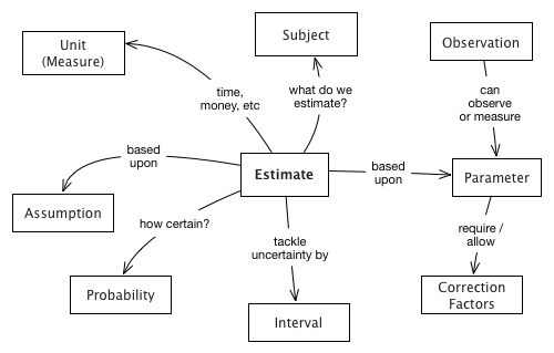
| Domain concept | Explanation | Example |
|---|---|---|
Estimation |
an approximation of any subject (here: issues, problems or remedies), which is needed because facts or real observations are not available or possible. |
|
Subject |
a recurring problem in the [System] or associated processes |
|
Parameter |
an important element or foundation of the estimation. |
|
Assumption |
a fixed setting for any parameter. See Section 5.9, “Explicit Assumption” |
|
Observation |
measure, count, calculate gather real data for parameters |
if every developer is concerned by the problem, we count their number. |
Interval |
between 15% and 25% |
3.3. Pattern and Practices for Evaluation
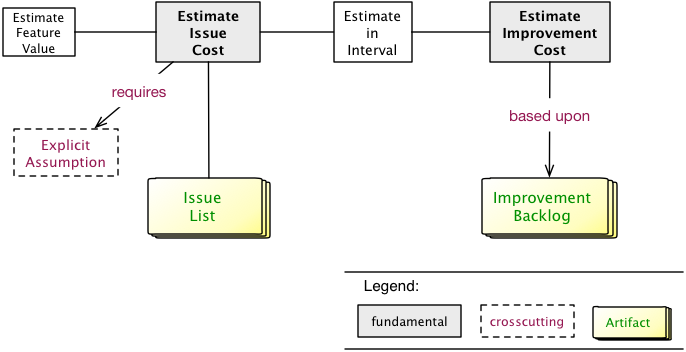
3.3.1. Estimate Feature Value
Intent
Estimate the (monetary) value of a given feature, so you can compare features of the system with each other.
Description
-
Involve business or management stakeholders, as they often have a clear notion of business value.
-
If you cannot determine real numbers available, use explicit assumptions
-
Instead of numbers, you might use categories or orders-of-magnitude (like small, medium, large). You should prefer numbers, though!
3.3.2. Estimate in Interval
Intent
Estimation is a guess, not a measurement. Estimates are uncertain, otherwise, they would be observations (or measurements!).
Description
Therefore, estimate in intervals, giving a lower and upper bound to your estimate. The difference between the two shows your confidence in the estimate. If this difference is relatively small, it shows high confidence.
| Be aware of the anchoring effect http://en.wikipedia.org/wiki/Anchoring |
Good estimates ensure that the estimated value will be contained in the interval with a very high probability.
Estimates often rely on assumptions - which should be Section 5.9, “Explicit Assumption”.
3.3.3. Estimate Issue Cost
Intent
Find out how much a given issue costs in units of money or effort in a period or for every occurrence.
Description
Finding out the cost of an issue usually requires estimation or guessing, so there are uncertainty and probability involved.
For example, if a server needs to be rebooted once every 24hrs and an operator needs 30 minutes to perform this reboot (and corresponding activities), then you can approximate the cost of this problem for, let’s say, a month:
5 workdays × 4 weeks × 30 min = 10hrs of operator’s effort.
If you multiply with (an approximated or averaged) wage, you get problem cost.
-
If possible, try to measure or observe instead of guessing or estimating.
-
If you cannot determine real numbers, and you need to guess, estimate or approximate, use Section 5.9, “Explicit Assumption”.
4. Improve
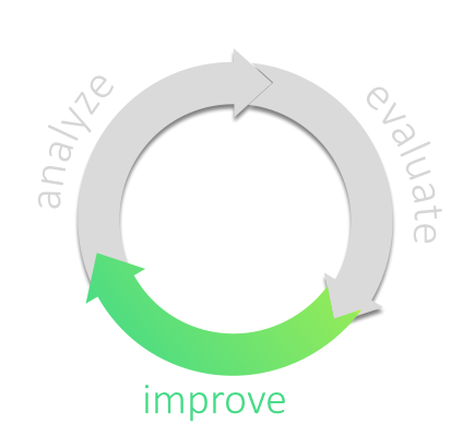
4.1. Goals
-
Execute and coordinate the improvement activities to eliminate problems and issues found during analysis. There is a whole bunch of practices devoted to this step, and we described the different approaches you can take to run the improvements.
-
Apply selected opportunities for improvement
-
Change code, structures, concepts or processes to achieve better software,
-
Reduce costs and/or technical debt,
-
Eliminate all kinds of issues,
-
Optimize quality attributes (like performance, maintainability, security),
-
Optimize operation and administration processes, thereby reducing effort and cost.
-
4.2. Structure of the Improvement Phase
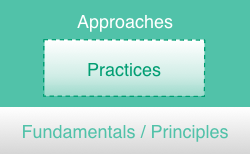
| Fundamentals |
Some principles which you should consider whatever steps you take on your road to improvement. |
| Approaches |
Overall (strategic, long-term) decisions how to tackle improvement, structured in several categories. Start with the overview or jump right to the details. |
| Practices |
fine-grained practices or patterns, structured in several categories. Start with the overview or jump right to the details. |
We’ll cover these topics in a top-down manner, starting with a brief overview of the respective categories available for approaches and practices.
4.3. Fundamentals
For improvement we take a number of fundamental principles for granted, depicted in Section 4.3, “Fundamentals”.
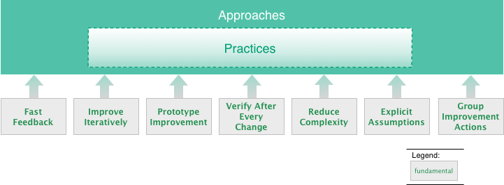
These fundamental principles surely belong to software engineering good practices - but we consider them indispensable for improvement projects.
| Fast-Feedback |
Get feedback to your actions and changes as early as possible, so you can adjust as quickly as adequate. |
| Improve Iteratively |
Improve in (potentially small) iterations and/or increments, so that change does not disturb or negatively affect the system, its associated processes and organization. Iterations are the prerequisite for our whole phased improvement. |
| Prototype-Improvement |
Verify the viability and effectiveness of improvements, usually in smaller scales with reasonable risks. |
| Verify-After-Every-Change |
Always make sure that changes, even minor ones, leave your system intact. (The awesome Jerry Weinberg has written up several examples of such failures). |
| Reduce Complexity |
Simpler solutions are most often easier to comprehend, maintain and operate. Therefore always strive for simplicity and the reduction of accidental, unnecessary complexity. |
| Explicit Assumption |
Compensate missing facts (especially requirements, goals, estimates, opinions) by explicit (written) assumptions about those facts. See Section 5.9, “Explicit Assumption”. |
| Group Improvement Actions |
Group related actions, so that they refer to similar entities and potential synergies are utilized. |
4.4. Improvement Approaches (Overview)

| Data Migration |
Keep your (valuable) data, and toss (or rewrite or otherwise change) your code. Oftentimes combined with approaches from the categories rewrite or restructure. |
| Rewrite |
Your system is broken beyond repair and you need to completely replace it by a new one. Rewrite approaches give you some ideas how and if that might work (spoiler: we fear that Big-Bang won’t work…) |
| Restructure |
Improve your system by restructuring your code in-the-large. Might involve extraction of certain functionalities, splitting your system, improving the modularization or strangulating certain (bad) parts of the system (and, of course, replacing those by better solutions). |
| Improve Modularization |
Subcategory of restructure: improve responsibilities within the system, improving the boundaries between components, improving interfaces and similar operations. |
| Brainsize |
Evidence from neuroscience suggests our working memory has a capacity of about four items [2]. That’s why smaller solutions tend to be more maintainable, as the cognitive load on the developers working memory is reduced. These "brainsizing" strategies can be used to reduce the amount of stuff, e.g. by splitting your system up, extracting certain parts into abstractions, or other ways to reduce LOC or other complexity metrics. Terms like microservices fall into this category. |
| Improve-Domain-Focus |
Subcategory of restructure:Clear separation of domain-related code from purely technical aspects has long been a useful design heuristic - but is still often violated. In addition, aspects belonging to similar areas of the domain should be implemented within the same building-blocks (in Domain-Drive Design terminology called Bounded Context). |
You find further information on the detailed approaches here.
4.5. Improvement Practices (Overview)
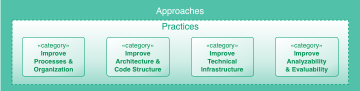
| Improve Processes and Organization |
Sometimes your issues originate in process or organizational root causes, meaning your development, rollout or operations processes are less efficient than they should be. This category adresses such problems. For details see Section 4.9, “Practices to Improve Processes”. |
| Improve Architecture and Code Structure |
All aspects of sourcecode may be subject to improvement - style, structure, dependencies, conventions, naming and the like. Furthermore, structure in the large (modules, components, interfaces) or crosscutting and technical concepts belong to this area of improvement. For details see Section 4.10, “Improve Architecture and Code Structure”. |
| Improve Technical Infrastructure |
Technical infrastructure encompasses both underlying hardware and software. For details see Section 4.11, “Practices to Improve Technical Infrastructure”. |
| Improve Analyzability and Evaluatability |
Make the system easier to analyze and understand, e.g. by improving logging, tracing or by introducing clearer structures. Enable or facilitate evaluation (e.g. of certain issues) by creating, collecting and managing certain numbers (metrics), either in development-, deploy- or runtime. For details see Section 4.12, “Practices to Improve Analyzability and Evaluability”. |
4.6. Approaches, Practices and Regular Development
In regular development (sometimes known as daily business) you will most likely intertwine your approach(es) with numerous practices - as depicted in Figure 20, “Integrating improvement approaches and practices with regular development”.
In both long- and short-term planning (yes - even in highly agile and iterative development models you’ll have such planning) you need to balance the following often conflicting goals:
-
short-term profitability by creating business value by delivering features or fixes to production.
-
long-term maintainability of the system by improving inner quality, improving code structure, technology choices and the like.
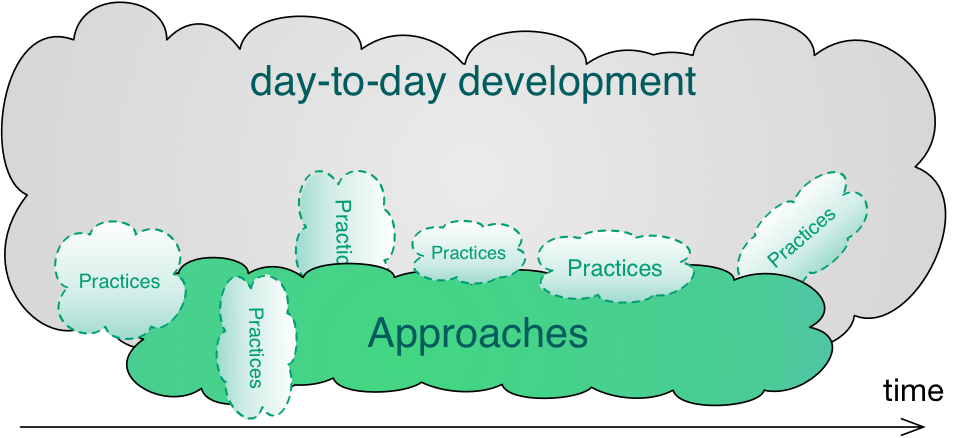
4.7. Improvement Approaches (Details)
One of the central decisions involves your long-term improvement-approach, the overall, long-range or strategic decision how you want to improve your system.
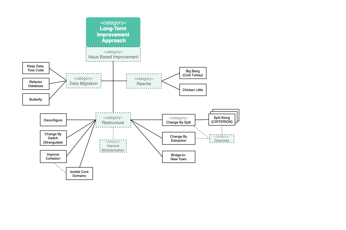
TODO: Describe Approaches
- Change-By-Split
-
Split up the original system into (not neccessarily distinct) parts. Clean-up those parts individually, and then evolve the parts independently.
- Keep-Data-Toss-Code
-
As value sometimes resides in data, keep data intact and replace the functional/service/process part of a system.
- Frontend-Switch
-
Start creating new backend parts. Frontend routes some requests to those new backend parts, others still to the existing ones. Gradually enhancing the new backend parts, frontend routes more and more requests to new backend.
- Big-Bang
-
Keep the existing system for a limited time, apply only critical bugfixes. In parallel, build a replacement system. Replace old by new at predefined time.
- Chicken-Little
-
Incrementally (11 steps) build a replacement system. You can choose between Database-First, Database-Last and Composite-Database Approach.
- Database-First
-
Do a Big-Bang migration of the database, incrementally implement new applications and interfaces and connect the legacy system to the new database by forward gateways.
- Database-Last
-
Keep the existing database for a limited time, incrementally implement new applications and interfaces and connect them to the legacy database by reverse gateways.
- Composite-Database
-
Combination of Database-First and Database-Last. Beside a forward- and reverse-gateway, there is a need for a transaction-coordinator.
- Butterfly-Methodology
-
Data-Migration Method without the need for gateways. Enables zero-downtime migrations by working with temporary data stores.
- Evolution
-
This approach has been extensively practiced by a Swiss Bank and published as a book. Underlying idea is to refactor those parts of the system(s) which are actually to be changed, especially to move all interfaces to new service standard and replace all legacy technologies and other couplings (via DB etc). Over time services should emerge that can be moved to a new platform altogether (from Mainframe to Java).
4.7.1. Big Bang Approach
Description
A big bang rewrite replaces an old system with a new system with one big bang deployment. The new system is developed from scratch. The opposite approach would be an incremental replacement, where individual parts get replaced step by step.
Experiences
Positive:
-
Basecamp rewrote their product successfully within a year. (Note: they kept the old and new system running in parallel and customers could decide to switch or not, therefore this is not a hard big bang)
-
An insurance company replaced a small system within 4 month by big bang
-
A multiple years running big bang replacement project of a governmental application has been successfully delivered in time and budget (but they also had no market pressure for new features)
Negative:
-
Chad Fowler wrote about all the failures he was involved (and the reasons)
-
Netscape’s market share dropped to almost zero (and stayed there), because of their rewrite
-
Borland and Microsoft wasted a lot of money with trying to rewrite Quattro Pro and Word (which eventually failed)
-
Logistics company lost 4 years and rewrote the system twice until they could proceed with new features
-
A data aggregation company estimated the rewrite to take 15 month, but it took 27 month and twice as much developers as originally estimated.
-
A telecommunication company failed twice to replace two of their old invoicing systems with a big bang approach due to incomplete requirements and an unrealistic time schedule. This led to a bad designed and buggy new system, which had both had to be rolled back from production.
Risks
Big bang replacement of medium and large systems have many risks, which shouldn’t be taken lightheaded. You need to make sure that you understand and communicate the risks and that risk, cost and benefit are worth it.
-
Software as a spec: Way too often, a big bang rewrite project has no proper requirements engineering. "Make it do what it already does." is an often heard answer on how a feature should be implemented. As Chad Fowler points out in his blog, this has two major drawbacks: 1) if you are not familiar with the old system you don’t know what questions to ask and 2) if you are familiar you certainly don’t remember every little corner (especially when you need to estimate effort this will go horribly wrong).
Therefore you need to reverse engineer the code base to write proper requirements. Since the software is in such a bad condition that it needs to be rewritten you can be sure that this is not an easy task. -
Your business will certainly not like the big bang rewrite, because it takes minimum one year, often two or three to fully rewrite a system. This means that your business won’t get any new features during that time and that could be a threat to the business itself. Governmental agencies might be fine with this, but the rest certainly not. Ask Netscape.
-
In many cases, the business is asking for new features for the old system, while the new system is still under development. You will then chase a moving target, which can be a long and painful journey. The old systems has certainly some dark corners and a few stakeholders want to get rid of them. This is what Chad Fowler calls a wish list. Now you’re at a point where you have to clearly write down the requirements, because the two systems go into two different directions.
-
The old system usually collected a lot of bad Technical Debt (that’s often the main reason we rewrite). In the beginning of the rewrite everything is good, the code is clean. But because you chase a moving target, need to implement new features or things that are just harder as expected, you are running out of time, which introduces a lot of bad Technical Debt in the new system. You replaced a badly implemented system with old technology with a badly implemented system using new technology.
-
The organisation creates often a culture of the "tiger team": the people who work on the new system get bragging rights. Expectations grow and are hard to manage.
-
The "Big Bang Day". Eventually you have to deploy the new system and migrate the data. This happens often big bang and is therefore a major risk.
-
As Joel Spolsky put it: "It’s important to remember that when you start from scratch there is absolutely no reason to believe that you are going to do a better job than you did the first time. First of all, you probably don’t even have the same programming team that worked on version one, so you don’t actually have "more experience". You’re just going to make most of the old mistakes again and introduce some new problems that weren’t in the original version."
Applicability
You should consider a rewrite (not necessarily big bang) for the following reasons:
-
Your application is totally unmaintainable, but it needs new features, because the market demands them. And:
-
Your application is rather small and can be rewritten in less than 3-6 month if you are in a domain where your customers don’t accept a longer time without new features
-
Your application can be rewritten in less than 6-12 month if you are in a domain where your customers totally accept a longer time without new features (or have no choice, e.g. internal applications or government)
-
-
You lost the source code and you have no other choice
-
Your platform is so old, that you need to buy hardware at eBay, because the current hardware is deprecated.
-
Your codebase is still pretty good, but you want your application to do things in a radical new way and incremental change doesn’t help you with that. You don’t want to replace the current system with a new one and keep the requirements as they are right now, but you want to build a better system for your users as well (= your main motivation).
-
Quality developers with experience in the technology you need are too hard to find
-
You have deprecated central software frameworks or hardware (It can’t be upgraded to support newer platforms/features)
-
There is new technology out there making things possible, which weren’t possible before (and those things give you a competitive advantage)
-
The cost of maintaining the current system is too high
-
Important (new) quality attributes like performance, availability or security cannot be met anymore and the changes needed to implement them are so substantial that a rewrite is necessary
-
Even simple bug fixes take too long because of the complexity of existing code and might introduce new bugs
-
New features take too long and cost too much because of the interdependence of the codebase (new features cannot be isolated and therefore affect existing features)
-
Deployment is hard or impossible to automate, takes too long and is really risky. In fact, it fails often.
-
Your data are inconsistent and causes surprised and/or angry users. Keeping the data consistent is extremely hard, because the data model and the code operating on the data model is a huge mess.
A big bang approach is possible, if you cannot or want to incrementally replace the system for the following reasons:
-
The new system should undergo a revolutionary improvement instead an incremental one for both, technology and functionality
-
The system is small enough that it can be rewritten quickly within a few month
-
You analyzed other approaches like Section 4.7.8, “Strangler Approach” or Seams and they could not help you approaching the problem incrementally
-
You and your stakeholders are aware and understand the risks and consequences of a big bang rewrite and want to go for it anyways (you might have good reasons to do so).
Consequences
-
You and your stakeholders are OK with
-
Not getting new features, rather less, for the time of the rewrite despite having higher cost (writing the new system and running the old one)
-
The new system will have less features than the old one (at least in the beginning)
-
The new system will have more bugs (because the old one is already battle-proved for a long time and the new one is not). Please be aware that it is naive to belief that you can deliver the new system almost bug free, because you already have the experience of the old system
-
-
In case the application cannot be rewritten within 3 months, you and your stakeholders need besides enough budget and manpower a lot of patience to rewrite the application completely. Getting impatient and rush into the release creates bad Technical Debt
-
You will have higher cost and risk of failure, but no benefit for your users. If you want to give your users a benefit, too, you cannot simply replace the old system with a new one, but you also need to rethink the way the application behaves in terms of usability, speed or flexibility. If you don’t want to incrementally improve your product, but rather introduce a revolution, the big bang rewrite is what you need
-
In case you rewrite the system using a new platform and language, there will be winners and losers regarding the change. Developers who are strong in the "old" technology will feel left behind unless they get a good chance in mastering the new technology. In any case, they will loose their strong expert position for some time and that alone causes tension and conflict.
References
-
Chad Fowler wrote a blog post series on The Big Rewrite
-
Joel Spolsky on Big Bang Rewrites: Things You Should Never Do, Part-I
-
David Heinemeier Hansson on when to fully rewrite a system
-
Dave Thomas about legacy innovation on IEEE Software
-
Discussion on Stackexchange
4.7.2. Chicken-Little Approach
Intent
Software-Migration with incremental steps to avoid or reduce the risks coming along with the Big Bang approach.
Description
Chicken Little was already described back in the 1990s of the last century by Michael L. Brodie and Michael Stonebreaker and is explained in their great book 'Migrating Legacy Systems' [1].
The name of this approach originates from a Walt Disney cartoon, where the protagonist Chicken Little is a very young hero who saves all with his cautious & conservative character. These are also highly essential & invaluable qualities in software migration.
The name 'Cold Turkey' for a Big Bang migration was also introduced by Brodie and Stonebreaker, which is a synonym for cold detoxification and therefore clearly describes the dislike of the authors in this kind of migration.
The central idea of Chicken Little is to create a composite system consisting of the legacy system and the new target system. Incrementally, components of the legacy system are replaced with components of the target system. The legacy system thereby shrinks and the target system grows.
The composition is implemented through gateways. They transfer both reading and writing requests to the respectively other system. A gateway can be a forward or a reverse gateway. A forward gateway is integrated into the legacy system and routes requests to the target system. A reverse gateway is part of the target system routing to the legacy system.
Brodie and Stonebreaker define Chicken Little as 11 steps. Each step is applied for every increment of the migration. An increment can be a use case or a bounded context. The execution of these 11 steps can be in any order and parallel; steps can be omitted.
-
Incrementally analyze the legacy system
First, it is necessary to understand the legacy system. Consequently reverse engineering is needed to find out the requirements, which in principle are valid for the legacy system as well as for the target system. Utilize documentation (if at all exists), but be aware that it is mostly outdated and incomplete. Reading legacy source code might be reasonable only in rare cases. Apart from that, interview the people who support, manage or use the legacy system. In doing so, consider the principle of need-to-know, otherwise, you can fall into analysis paralysis, which results in delayed development.
-
Incrementally decompose the legacy system structure
In this step, the legacy system is modified to achieve a decomposable structure (3-layer-architecture) or well-defined interfaces. This is required for optimally integrating a gateway (step 7). The cost of this procedure depends on the current structure of the legacy system and might even be unachievable.
-
Incrementally design the target interface
GUIs or APIs of the target system are designed and specified, including a general idea of the architecture of the target system. A decision is reached whether gateways should be built.
-
Incrementally design the target application
Similar to the previous step, business logic and rules must be designed and specified.
-
Incrementally design the target database
Finally, the database must be designed to meet data requirements. A prerequisite is understanding the legacy data store which might be complex, especially if it is not a relational database.
-
Incrementally install the target environment
First of all, the requirements for the target environment must be identified. Later on, hardware and server machines will have to be installed and tested, a deployment strategy is developed, and a concept regarding user management finalized.
-
Incrementally create and install the necessary gateways
Now one or more gateways have to be implemented. The best way a gateway works is for fully decomposable systems (3-layer-architecture). For that case either use:
-
forward database gateway, see Section 4.7.3, “Database First Approach”
-
reverse database gateway, see Section 4.7.4, “Database Last Approach”
-
forward and reverse database gateway, see Section 4.7.5, “Composite Database Approach”
In not fully decomposable systems the gateway must be placed on a higher level, for example between presentation and logic tier. It might be possible to receive a 3-layer-architecture in the legacy system by refactoring (step 2). As the target system grows and the legacy system shrinks, a gateway is reduced accordingly. In the situation of having both a forward and a reverse gateway, this results probably in redundant data in the legacy and target database. Keeping consistency is challenging and distributed transaction (2-phase commit) might be necessary.
-
-
Incrementally migrate the legacy database
The target DBMS is installed, and the DB-schema resulting from step 5 is implemented. The data has to be migrated, and a gateway is utilized for legacy application calls.
-
Incrementally migrate the legacy application
Modules with business logic based on step 4 will have to be rewritten. The selection of these migrated modules is based on technical and organizational criteria. Take that one which is the simplest, most needed, or that one facing the highest risk.
-
Incrementally migrate the legacy interface
GUIs and APIs designed in step 3 are implemented.
-
Incrementally cutover to the target system
Cutover is the process of switching users and their operations from the legacy to the target system. Then legacy components can be discarded. The smaller these steps are, the lower the risk. If one step fails, only this step has to be repeated and not the whole project.
Risks
-
Gateways can be highly complex. Implementing a forward gateway may not be possible due to the structure of the legacy system.
-
It may be difficult to keep consistency between the legacy and the target database.
-
A composite system is highly complex and not easy to comprehend for new team members. The loss of experienced developers and their know-how are even more severe.
-
Estimating time and budget is difficult. When the migration begins, it is challenging to estimate how long it will take and how much it will cost.
-
Also, reverse engineering is tricky. There is the danger of missing features, so early feedback of users is invaluable.
Applicability
Use this approach (or the main ideas) when you need to migrate in a safe and incremental way. It is highly recommended for mission-critical systems.
Consequences
Software migration is not easy, and one will need patience and endurance. Migration projects can last several years. For that, a strong team is required.
References
-
[2] Matthias Möser, Abschied nehmen vom Legacy-System, Java Magazin 3.18, https://entwickler.de/leseproben/legacy-systeme-agil-ersetzen-579827753.html
4.7.3. Database First Approach
Description
The Database First approach (also called the Forward Migration Method) involves the initial migration of legacy data to a modern, probably relational, Database Management System (DBMS) and then incrementally migrating the legacy applications and interfaces. While legacy applications and interfaces are being redeveloped, the legacy system remains operable. This methodology falls within a group of methodologies which allow for the interoperability between both the legacy and target systems. This interoperability is provided by a module known as Gateway: a software module introduced between components to mediate between them. Gateways can play several roles in migration, insulating certain components from changes being made to others, translating requests and data between components or coordinating queries and updates between components.
The concrete gateway used by the Database First approach is called Forward Gateway. It enables the legacy applications to access the database environment in the target side of the migration process, as shown in Fig. 1. This gateway translates and redirects these calls forward to the new database service. Results returned by the new database service are similarly translated for used by legacy applications.
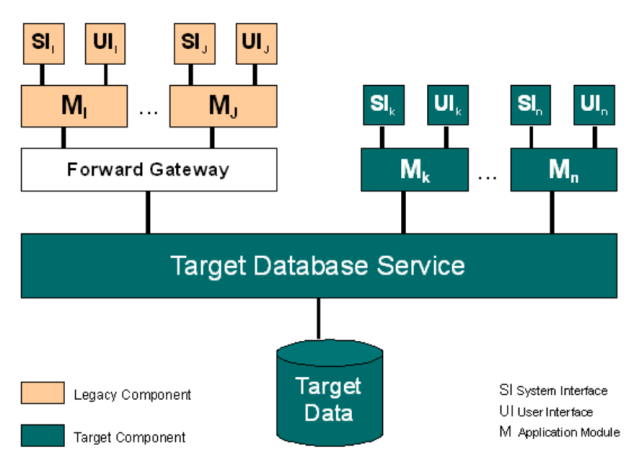
The main advantage of this approach is that once the legacy data has been migrated, the latest programming languages and reporting tools can be used to access the data providing immediate productivity benefits. The legacy system can remain operational while legacy applications and interfaces are rebuilt and migrated to the target system one-by-one. When the migration is complete, the gateway will no longer be required and can be decommissioned as the old legacy system is shut down.
There are several disadvantages to this approach, in particular, it is only applicable to fully decomposable legacy systems where a clean interface to the legacy database service exists. Also, before migration can start, the new database structure must be defined. The major risk with this activity is that the structure of the legacy database may adversely influence the structure of the new database.
The Forward Gateway employed can be very difficult, and sometimes even impossible, to construct due to the differences between the source and the target in technology, in database structure, constraints etc..
Overall this is a rather simplistic approach to legacy system migration. The migration of the legacy data may take a significant amount of time during which the legacy system will be inaccessible. When dealing with mission critical information systems this may be unacceptable.
(taken from BISBAL, J. et.al.)
The database first approach (also known as forward migration method) provides for legacy databases to be moved unchanged into a relational database management system (RDBMS) to incrementally develop the user interface and the applications on the target system. But there is a need for a gateway to accept database calls from the legacy system and to redirect them to the new database system.
As BATEMAN and MURPHY say, there are a few problems and challenges:
-
to develop a forward gateway can be complex or even impossible, because there can be big differences in technologies according to structure, constraints, query languages and semantic heterogeneity.
-
usually reverse gateways are available on the market. Vendor tools often enable remote database access for example by sql. The purpose is that the legacy system becomes a big database server.
-
a pre condition to develop a forward gateway is, that the legacy system has clearly specified interfaces to the database layer. If this is not the case, there have to be expensive modifications to the applications, which can be time and cost intensive.
-
maybe there are a lot of external systems like reports, relying on the interaction with the legacy system. These systems have to be localized and analysed, so that they won’t crash after the migration.
-
the new database structure has to be designed and the data mapping has to be implemented before the migration can start. A problem can be data structures, that can not be adopted to the new data structure.
The main advantage of the database first approach is, that after the big-bang migration of the database, new programming languages and reporting tools can be used with the new database system. New applications can be developed in parallel to the legacy system, step by step, module by module, without an influence on the legacy system. As the migration is finished, the gateway can be deactivated and the legacy system can be shut down.
References
-
BATEMAN, A. und J.P.MURPHY: Migration of Legacy Systems. Working Paper: CA-2984, School of Computer Applications, Dublin City University, Ireland 1994
-
BISBAL, J. et.al.; A Survey of Research into Legacy System Migration. Technical Report TCD-CS-1997-01, Computer Science Department, Trinity College Dublin, 1997. http://citeseerx.ist.psu.edu/viewdoc/summary?doi=10.1.1.50.9051
4.7.4. Database Last Approach
Description
The Database Last approach, also called the Reverse Migration Method, is based on a similar concept to the Database First approach and is also suitable only for fully decomposable legacy systems. Legacy applications are gradually migrated to the target platform while the legacy database remains on the original platform. The legacy database migration is the final step of the migration process. As with the Database First approach, a gateway is used to allow for the interoperability of both information systems. In this case a Reverse Gateway enables target applications to access the legacy data management environment. It is employed to convert calls from the newly created applications and redirect them to the legacy database service, as shown in Fig. 1.
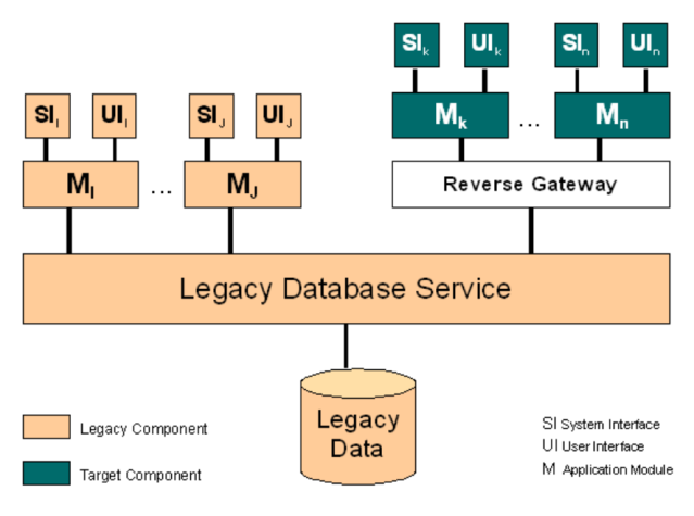
If the legacy database service is to be migrated to a relational database management service, then the target applications will be developed completely with SQL calls to the data service. It is these calls that are captured by the Reverse Gateway and converted to the equivalent legacy calls. The Database Last approach has a lot in common with the client/server paradigm. The legacy database takes on the role of a database server with the target applications operating as clients. There are commercial products available which effectively act as reverse gateways.
The Database Last approach is not without its problems however. Performance issues can be raised with regard to the gateway. The Reverse Gateway will be responsible for mapping the target database schema to the legacy database. This mapping can be complex and slow which will affect the new applications. Also many of the complex features found in relational databases (integrity, consistency constraints, triggers etc.), may not be found in the archaic legacy database, and hence cannot be exploited by the new application.
This approach is probably more commercially acceptable than the Database First approach as legacy applications can continue to operate normally while being redeveloped.
However, the migration of the legacy data will still require that the legacy system be inaccessible for a significant amount of time. When dealing with mission critical information systems, this may be unacceptable
(taken from BISBAL, J. et.al.)
References
-
BISBAL, J. et.al.; A Survey of Research into Legacy System Migration. Technical Report TCD-CS-1997-01, Computer Science Department, Trinity College Dublin, 1997. http://citeseerx.ist.psu.edu/viewdoc/summary?doi=10.1.1.50.9051
4.7.5. Composite Database Approach
Description
In Composite Database approach, the legacy information system and its target information system are operated in parallel throughout the migration project. The target applications are gradually rebuilt on the target platform using modern tools and technology. Initially the target system will be quite small but will grow as the migration progresses. Eventually the target system should perform all the functionality of the legacy system and the old legacy system can be retired.
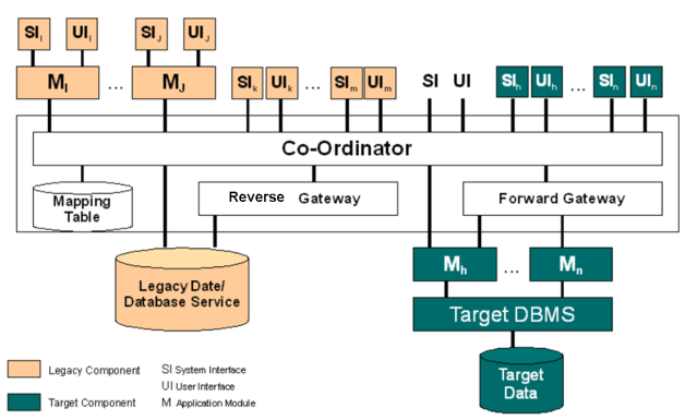
During the migration, the old legacy system and its target system form a composite information system, as shown in Fig. 1, employing a combination of forward and reverse gateways. The approach may involve data being duplicated across both the legacy database and the target database. To maintain data integrity, a Transaction Coordinator is employed which intercepts all update requests, from legacy or target applications, and processes them to identify whether they refer to data replicated in both databases. If they do, the update is propagated to both databases using a two-phase commit protocol as for distributed database systems.
Analysing non-decomposable legacy components can be very difficult. In the worst case the component must be treated as a black box. The best that can be achieved is to discover its functionality and try to elicit as much legacy data as possible. Sometimes using existing legacy applications (e.g. database query, report generation and access routines) are the only way to extract the legacy data. Once the functionality has been ascertained, the component can be redeveloped from scratch. It can often be very difficult to identify when legacy data or functions are independent. In many cases they may simply have to be replicated and target copies coordinated until the entire legacy system can be safely retired.
The Composite Database approach eliminates the need for a single large migration of legacy data as required in the Database First and Database Last approaches. This is significant in a mission critical environment. However, this approach suffers from the overhead not only of the other two approaches but also the added complexity introduced by the coordinator.
(taken from BISBAL, J. et.al.)
Applicability
The Composite Database approach is applicable to fully decomposable, semi-decomposable and non-decomposable legacy systems. In reality, few legacy systems fit easily into a single category. Most legacy systems have some decomposable components, some which are semi-decomposable and others which are non-decomposable, i.e. what is known as a Hybrid Information System architecture.
References
-
BISBAL, J. et.al.; A Survey of Research into Legacy System Migration. Technical Report TCD-CS-1997-01, Computer Science Department, Trinity College Dublin, 1997. http://citeseerx.ist.psu.edu/viewdoc/summary?doi=10.1.1.50.9051
-
Praful Todkar wrote the blog article "How to extract a data-rich service from a monolith" on martinfowler.com
4.7.6. Butterfly-Methodology
Intent
Data migration method without the need of gateways. Enables zero-downtime migrations by working with temporary data stores.
Description
The Butterfly methodology focuses on data. There is no need for a gateway like in the Chicken-Little Strategy. At the beginning there is an initial data migration, which can be used to develop the new application without an influence on the legacy system. When the migration process starts, the data of the legacy system gets freezed and set to read-only. From now on data changes will be stored in a temporarily store. A Data Access Allocator (DAA) decides, if a request has to be send to temp store (for already changed data) or to the original database. With the help of a Chrysalizer (a data transformator), where transformation rules are implemented, all the data from the read-only database will be moved to the new system. No data will be lost, because changes are written to the first temp store. When the initial migration is finished, the data of the temp-store will be migrated, changes will be written to a second temp store and the first one is set to read-only. This process will continue until the time period of the migration is so short, that there will be no change in between the two stores anymore. At this moment, the legacy system can be shut down, the last temp store gets migrated and the new system is turned on. This approach helps to migrate a productive system without downtime. Another pro is, that the process can be canceled at any time by rolling back the temp stores. It is also possible to execute tests of the parallel development with actual data. A problem can be the amount of hardware that is needed to keep all the temp stores if you have a massive amount of data. Also it can be very expensive to implement the DAA.
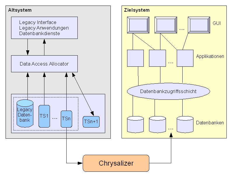
Risks
If the Butterfly Method will be successful depends on the factor v / u, where u is the speed of the Chrysalizer and v the speed of the DAA to setup new temp stores. If v = 0 this approach is similar to the Section 4.7.1, “Big Bang Approach”, if v > u the migration will never end.
Consequences
Enables zero downtime migrations by working with temporary data stores. If the amount of data is huge, there is a need for a lot of hardware.
Critical success factors are:
-
a very good understanding of the old and new system
-
an initial migration without errors / mistakes
-
a fast Chrysalizer
-
a efficient Data Access Allocator
4.7.7. Change-by-Split Approach
Prerequisites
The system has several distinct (usually nearly disjunct) user groups. For each of these groups, slightly different business rules, processes or other requirements hold.
Intent
Maintain and evolve a few smaller systems, instead of one big monolith. Reduce time-to-market, work in smaller teams that individually become more focussed.
Description
-
Identify different user groups, at best disjunct. An example: For an online E-commerce system, such groups might be private and corporate customers.
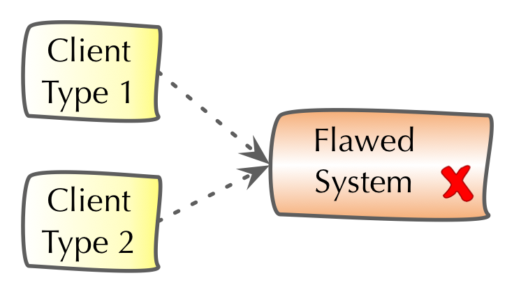 Figure 26. Change-by-split, initial situation
 -
As a preparation, copy the whole system, with all sources and everything required to develop, build, test and run the system. This might include databases or other middleware. Every part should be completely independend of the others.
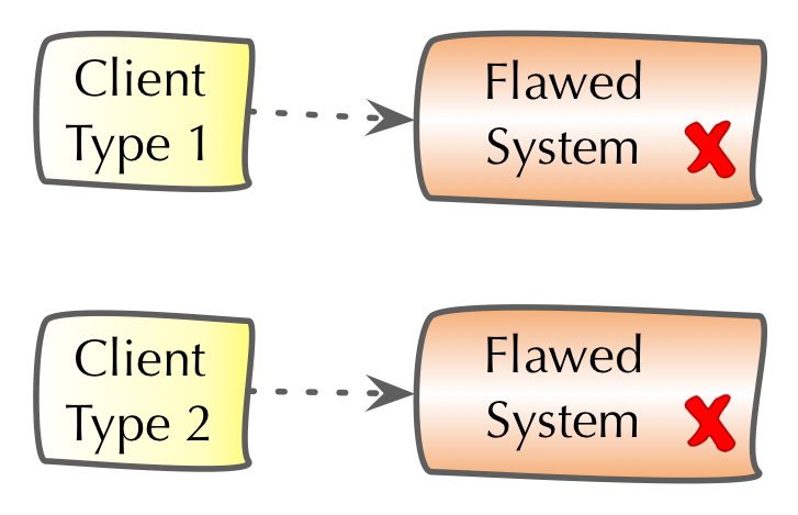 Figure 27. Change-by-split, system copied for every user type/category
 -
Identify commonalities among these different user groups, crosscutting concerns that every user group needs in a common way. In our E-commerce example, those might be pdf-generation, user/role management or the like. Factor out those commons into a separate module/subsystem, which is used by (likely all) other split systems.
Make part of the whole development team responsible for the commons.
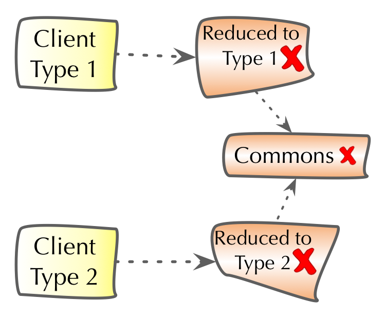 Figure 28. Change-by-split, factored out commons
 -
Now you can optimize and/or refactor the commons subsystem. As its code is now centralized, that task might become somewhat simpler than within the original legacy system. At the same time, remove all commons-code from the split systems - reducing them in size.
Split the rest of the whole development team according the split systems. Make one developer group responsible for one split system.
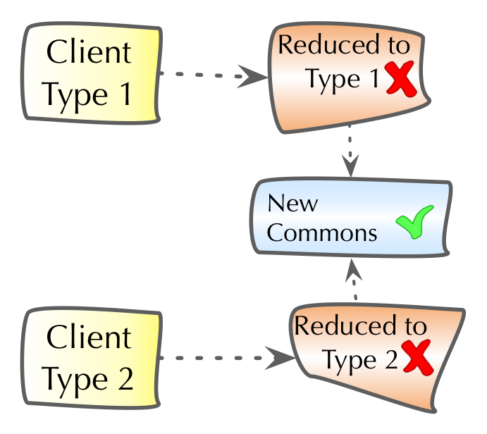 Figure 29. Change-by-split, reduced splits, optimized commons
 -
Now for the core of this approach: Aggressively reduce every split system to its core: remove all code not required for the split-specific user group, remove all code that can also be handled by the Commons subsystem. This step might be performed parallel to optimizing the commons.
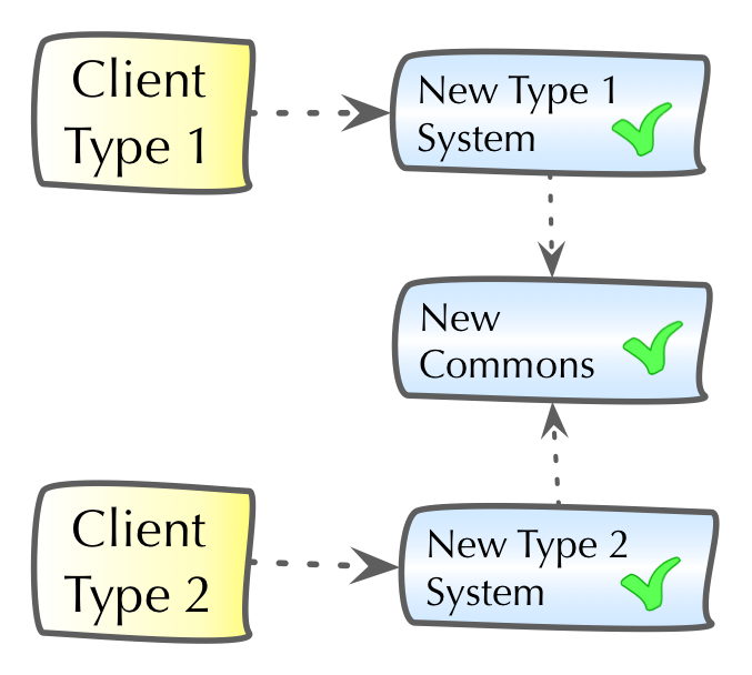 Figure 30. Change-by-split, all split systems reduced/optimized
This final step might need extensive preparation, e.g. by creating user-category specific unit-/integration-/acceptance tests. Reducing unneeded code can be quite difficult, if the original code has (extremely) high cyclomatic complexity or is very difficult to understand for other reasons (configurability, strange technologies, using strange/outdated/proprietary frameworks etc.).
Steps 4 and 5 might be interchanged or done in parallel.
Experiences
-
An niche-market software supplier could reduce their 2+Million LoC moloch to five split systems, each having approx 300kLoC plus one commons-system.
Time-to-market for feature requests was reduced from 12 weeks before the splits to 1 week afterwards. Team size of 50+ was reduced to 8+ people. A retrospective approx 9 month after the split showed significant higher customer satisfaction and (!) a significant increase in developer happiness (probably reducing know-how drain). The split-approach was regarded as a success by business, management and technical stakeholdes.
Risks
-
Creating several copies of a large system plus infrastructure can be expensive and resource-intensive.
-
Identifying really disjunct user groups might be impossible for several business domains, rendering this approach useless.
-
The required team-split might pose organizational challenges, as a currently productive (albeit large) team has to be disrupted.
-
It might be difficult to define appropriate interfaces for the factored-out commons. If these commons are overly scattered throughout the legacy code, this extraction might be impossible, making the resulting split systems more complicated than they should be.
-
If business code is overly tangled, having very high cyclomatic complexity, it can be arbitrarily difficult to remove those parts that are not required for a single user type/category. Analyzing such code segments should be performed my members of several split-teams.
-
Associated processes (like requirements, test, documentation and operations) of the split systems might become more difficult to manage in the first phases of a split. Due to the reduced sizes of split systems, it might be likely such processes will become simpler over time.
Applicability
Whenever a legacy system servers more than one homogeneous user group, this split approach might be appropriate.
The business processes for the various user groups need to be sufficiently different from one another - otherwise splits would merely create duplicate functionality.
Consequences
-
Instead of having to manage one single (but large) system, you will have to manage (develop, change, operate) several (smaller) systems. This might be especially relevant for operations effort.
-
Instead of having to manage one single development team, you will have to manage several.
-
All "things" you are dealing with (code, data-structures, data, processes) will become smaller, reducing complexity of these "things".
-
"Time-to-market" of your split systems will be lower (as development will be faster) - maybe coordination and management effort might increase.
Proposed practices
-
Find a relatively small user-group and pilot (try-out) this approach.
-
Involve the affected user groups as early as possible to facilitate possible required changes on their side.
-
Try to to identify potential neuralgic sections within the code, that do not belong into the factored-out commons and will likely affect several of the split systems. Try to minimize the effort required to analyze and untangle such sections by gathering people from various split-teams.
-
Don’t try everything at once: Spread out step 5 (optimize splits) over several, possibly many, development iterations or releases. Let the split teams become comfortable with their reduced split systems.
4.7.8. Strangler Approach
Description
Rewriting an old system with the Section 4.7.1, “Big Bang Approach” is a risky endeavor. It is harder than you might think at the beginning.
An alternative way is to gradually create a new system around the edges of the old, letting it grow slowly over several years until the old system is strangled. The most important reason to consider a strangler application over a cut-over rewrite is reduced risk (it might cost more to do a strangler, but that’s the price of risk reduction) [1].
Paul Hammont depicts the strangler approach as follows [2]:
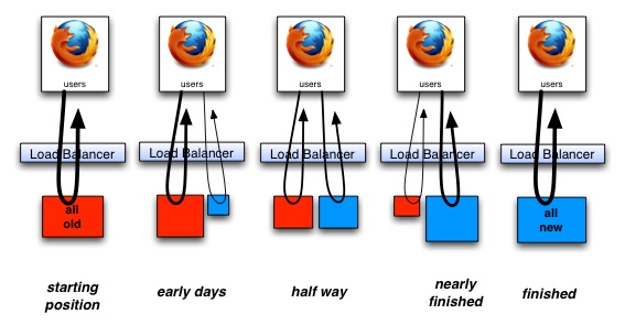
He discusses two ways of achieving the goal of moving from the (red) old system to the (blue) new system:
-
With adding new features
-
Without adding new features
Deciding to go for the first strategy means that you can still keep your business happy because you are still able to deliver new features. However, this approach will take longer than the second one.
Experiences
-
Paul Hammont reports the following positive with his case studies:
-
Airline Booking System: the C application which was stable but hard to grow (and find developers) has been incrementally replaced by a Spring stack based application. A load balancer routed the requests to either the C or the Spring application. They introduced session store used by both systems (the C++ application needed to be adjusted for this).
-
Trading Company’s PowerBuilder based Rich Client: you cannot integrate a new rich client into a new one, so the team decided to run two client applications in parallel for the energy traders, adding more and more functionality to the new (Swing-based) client. The users weren’t forced to use one or the other, but the team made the new application so compelling that they wanted to. Google is (as I heard from a Googler) doing similar approaches to their internal systems, which are replaced by new systems all the time and you need to decide when to switch.
-
National Supermarket’s internal planning system based on Swing and a major database is moving into a Rails and Java Microservices based web application. Since the two technologies are also very different, there is no smooth way of integrating the old and the new system, they have to exist in parallel (it is an internal system)
-
Used consumer goods magazine’s web portal - a move from Oracle Endeca to Java/JavaScript. First, they changed the Oracle frontend that it looks like the new system. Then they integrated a little piece of new functionality from the new stack into the website. The first strangler release took 6 months, then the delivered regularly.
-
-
Nat Pryce reports failed projects and challenges using the strangler pattern [3]:
-
"I’ve seen critical systems that have suffered both of these fates, and ended up with about four or five "strategic architectural directions" and "future state architectures". One large multi-site project ended up with eight different new persistence mechanisms in its new architecture."
-
"Another ended up with two different database schemas, one for the old way of doing things and another for the new way, neither schema was ever removed from the system and there were also multiple class hierarchies that mapped to one or even both of these schemas."
-
Risks
-
You need to overcome the lack of will to actually finish the strangling (usually political will from non-technical stakeholders manifested as lack of budget). If you don’t completely kill off the old system, you’ll end up in a worse mess because your system now has two ways of doing everything with an awkward interface between the two. Later, another wave of developers will probably decide to strangle what’s there, writing yet another strangler application, and again a lack of will might leave the system in an even worse state, with three ways of doing things [1].
-
You need to have consensus across the development team(s) on the future state of the architecture and how to get there. If everyone runs in another direction, then you end up with a new system, which is also hard to maintain.
-
If you’re introducing technologies that are new to the team or to support/maintenance staff (e.g. adding reliable async messaging to what is currently a synchronous three-tier client/server architecture) then you have to ensure that there are experienced technical leads on the project who know how to build systems with that technology and support those systems. And those tech leads have to stick with the project for some time after the old app has been fully strangled. Otherwise, the architecture will degrade as inexperienced developers modify it in ways they know but not in ways that fit with the new architecture [1].
-
Strangling creates a layer of goo and there is a risk that this layer becomes a mess, too.
Applicability
-
A big bang replacement is too risky and/or your business wants you to constantly deliver new features and does not accept a 1-3 years break for the big rewrite.
-
"Cost of Delay" of not moving to the new platform as early as possible is higher than the cost of running two systems in parallel
Proposed practices
Paul Hammant recommends the following practices [2]:
-
You really should phase the strangulation. Keep your larger application in a continually deployable state while working on it. The first go live after a month or so of work, then every two weeks after that at least or you’ll fail. That would probably via project cancellation by a checkbook-holding sponsor.
-
Do enhancements or new "business value" work concurrently with strangulation, while getting all to agree that both are happening. As you work on the strangulation, a decent percentage of work should be enhancements too. This allows value to be associated with each release from the point of view of the people paying for it. ROI and all that isn’t just abandonment of costly end-of-life IT choices, it is about tangible changes for the better. From top to bottom, everyone needs to agree that both are happening.
-
The additional of integration and functional test suites as a safety net is key. This is particularly true for when the old technology did not have unit test coverage. The functional tests will be able to step between old and new (and back), to prevent surprises.
-
Understand that Non-Functional Requirements (NFRs) that don’t directly cheapen the re-implementation may jeopardize the initiative. Jeopardize in the "courting cancellation" territory again. Various authority figures may have pet technologies to include or things to exclude. The test is whether the dev team cranking stuff out agrees or not.
-
Agile methodologies optimize everything for maximized developer throughput and phased deliveries to production. You will not manage this with waterfall, unless you want glacially long intervals between production pushes. The Pols/Stevenson white paper drills much further into the Agile aspects.
-
Lastly, you should always be aware that there could be functionality and context hidden within the old application that people have forgotten about, and that a team of business analysts assigned to reverse engineering behaviors might also miss. This is a risk for any "rewrite" though.
References
-
[1] Martin Fowler about the Strangler Application
-
[2] Paul Hammant’s blog post with practices and case studies
-
[3] Discussion on StackOverflow with Nat Pryce and Ira Baxter
-
Michael Feathers speaks on Hanselminutes about the Strangler Application
4.8. Improvement Practices (Details)
Practices, in contrast to approaches, are the short-term or tactical improvements.
We already explained the categories of these improvement practices in Section 4.5, “Improvement Practices (Overview)”. Here we dive into more details, structured along these categories:
-
Improve Processes,see Section 4.9, “Practices to Improve Processes”
-
Improve Architecture and Code Structure, see Section 4.10, “Improve Architecture and Code Structure”
-
Improve Technical Infrastructure, see Section 4.11, “Practices to Improve Technical Infrastructure”
-
Improve Analyzability, see Section 4.12, “Practices to Improve Analyzability and Evaluability”
4.9. Practices to Improve Processes
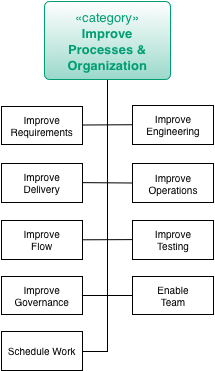
For an overview of other improvement practices, see Section 4.5, “Improvement Practices (Overview)”.
One way to improve the processes is to resort to Mob Programming for onsite teams or Remote Mob Programming for distributed teams.
4.10. Improve Architecture and Code Structure
| This category contains a fairly large number of practices. |
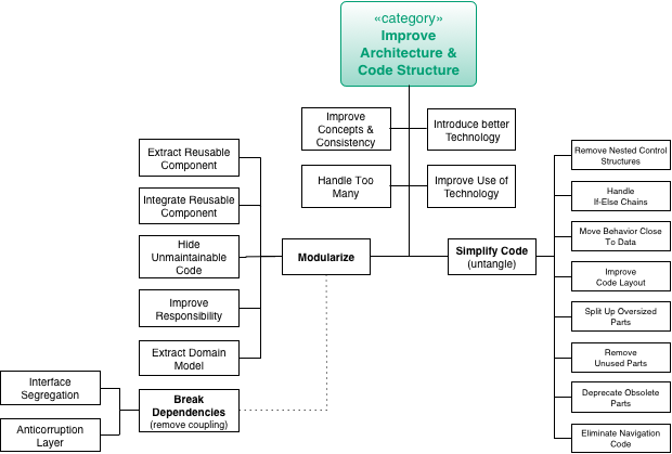
For an overview of other improvement practices, see Section 4.5, “Improvement Practices (Overview)”.
4.10.1. Architecture and Code Practices in Detail
(given in alphabetical order)
4.10.2. Anticorruption Layer
Intent
An anticorruption layer is a logical layer that provides a stable interface to (potentially) volatile software components. As long as this interface remains untouched developers can implement changes or even replace their own or third-party software without affecting the clients of this interface.
Description
The original definition [Evans03, p. 365]:
Create an isolating layer to provide clients with functionality in terms of their own domain model. The layer talks to the other system through its existing interface, requiring little or no modification to the other system. Internally, the layer translates in both directions as necessary between the two models.
Domain Driven Design
Experiences
Here are some real-life experiences:
-
Anticorruption layer for a search-index to defer the decision if the best performance can be achieved with Elastic Search, Solr or a self-developed Lucene index.
Applicability
Apply this pattern when clients shall be protected from internal changes in a module or subsystem.
Consequences
-
Allows to (ex)change software elements without affecting depending components
-
Introduces one more level of indirection and thus may increase complexity
Related Patterns
-
[Isolate-Changes], as an alternative or complimenting approach
-
[Bulkhead], introduces stability boundaries within applications or systems by segmenting runtime resources.
References
-
[Evans03] p. 364ff.
4.10.3. Change-by-Abstraction Refactoring
Prerequisites
Intention to change or replace a cohesive piece of code with a lot of incoming (afferent) dependencies. A common example is replacing homegrown ORM or plain SQL with a standard tool or exchanging a logging library for another with incompatible interfaces.
Description
-
Mark the Method or Class you would like to replace as deprecated.
-
Introduce an abstraction that is implemented by the old implementation. If the API of the new solution differs, consider the Adapter Pattern to perform

-
Incrementally move all the calls where the deprecated Class/Method is still being used to use the new API instead.
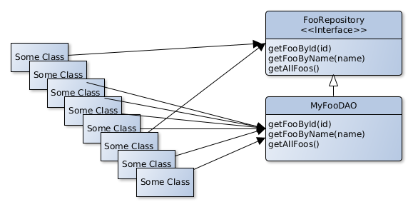
-
You can now implement and start testing the new functionality by deriving it from the abstraction you introduced in step 2.
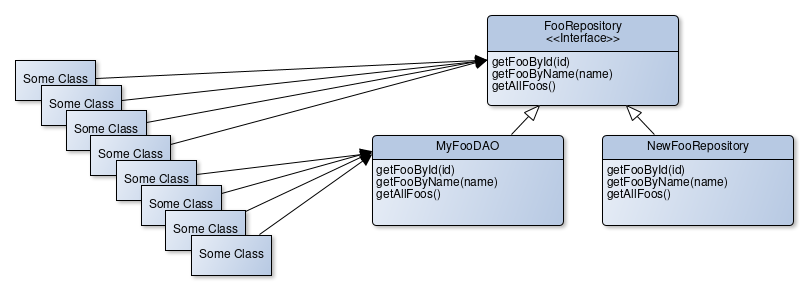
-
When all the places where the deprecated Class/Method is called directly are moved to the abstraction, you can use a feature toggle in a proxy class that implements the common abstraction to toggle between the old and the new implementation.
-
If you made sure the new functionality performs well enough, you can remove the deprecated implementation and possibly the abstraction.
Related patterns/names
This method is also known as "Branch by Abstraction" and a smiliar technique that goes under the names "Parallel Change" or "Expand and Contract" exists, where the abstraction step is skipped and callers are migrated to a new method/object immediately.
This approach works best when it is used in combination with Section 4.10.6, “Introduce Boy Scout Rule”.
Risks
Too many of these half-performed incremental refactorings will leave your code base in a mess. You still need to finish, what you start.
Consequences
-
Teams can collaboratively move code towards a new implementation by replacing calls to deprecated methods/classes with calls to the abstraction, even in parallel.
-
The refactoring can be made incrementally.
-
The build will remain "green", even when the refactoring is unfinished.
-
The abstraction enables comparison of the behaviour of the old to the new implementation in production or testing environments to make sure that the new implementation matches the old behaviour.
References
http://continuousdelivery.com/2011/05/make-large-scale-changes-incrementally-with-branch-by-abstraction/
http://paulhammant.com/blog/branch_by_abstraction.html
http://www.alwaysagileconsulting.com/application-pattern-verify-branch-by-abstraction/
http://martinfowler.com/bliki/BranchByAbstraction.html
https://printhelloworld.de/posts/refactoring-in-baby-steps/
https://www.branchbyabstraction.com/
4.10.4. Improve Logging
Intent
Employ sophisticated logging mechanisms such as modern logging frameworks, distributed log collection and visualization tools in order to gain more detailed information about the system during runtime with a minimal or predictable performance impact.
Description
While some time ago it was quite common to output log statements to standard out, people usually use logging frameworks nowadays that give more control about what should be logged and where the log entries should go.
However, it turns out that such logging frameworks have some feature gems that are not widely known or used. To name a few:
-
Diagnostics Contexts (also known as Mapped Diagnostics Context (MDC) or Nested Diagnostics Context (NDC)) help to store additional context information for all succeeding log statements. Usage examples for such contexts are the login name of the current user, correlation IDs in order to enable cross-application log tracing or transaction IDs to have the possibility to filter all log entries that belong together.
-
Additional log levels or markers help to make it easier to filter the log stream. It is a good advice to think about the marker and log design at the beginning of the project and try to agree on a common way to phrase log statements.
-
Asynchronous appenders (i.e. log emitter) allow high-throughput logging, which lower impact on the application’s performance.
-
Structured log formats produce a machine-readable output. Usually, log files are written using a more or less standardized text output. Log files in XML or JSON can be parsed and digested easily and allow for better filtering since more information, like diagnostics contexts, is always available in these formats.
-
Filters enable context-based logging and can dispatch log entries to different log appenders. For instance it is possible to log warnings only but switch to debug logging for a specific user.
In some environments it turns out to be problematic to rely on a single logging API. This could be the case if the application runs within a container or container-like framework that already employs a configured logging framework. In order to be independent of conrete logging frameworks, logging facades like SLF4J should be preferred over using the framework’s API directly.
Despite the focus on the software development, logging is also an operations topic. Often it turns out to be difficult to get recent log files from the operations team. Another pain point is that useful log information is scattered across multiple log files, stored at different locations on different systems. Log aggregation tools such as Splunk, Logstash, Apache Flume or fluentd can consume and unify log data from different sources (e.g. files, syslog, network), can trigger alerts or index the log stream in order to make them searchable. Now, with tools like Kibana, log data of a system of systems can be easily analyzed and visualized. Correlation IDs contained in the logs can be used to trace certain business-related requests across multiple distributed systems easily.
Using such features makes the problem analysis easier and more data is available in a standardized fashion.
Experiences
Most projects write log files in a more or less sophisticated fashion, in many cases log messages are phrased in a rather unstructured way. It turns out that a well-designed logging concept helps to make the log stream easier to understand. This concept should provide some guidelines regarding which log level should be used in which situation, how the wording of log messages could be unified and which additional log levels or markers shall be used for what purpose.
|
In a customer project we used an object-relational-mapping (ORM) tool for a database independent access layer. The data access was inherently transactional and created a lot of database traffic so that deadlock situations on the database were expected and properly handled with a delayed retry mechanism. While this approach worked quite well, we got frequently complaints from the operations team, which reported a number of ERROR log messages along with longish stacktraces that set their alarm bells off. These log messages were written by the ORM tool whenever a DB deadlock was experienced. Since the application could perfectly deal with this situation this was not an error anymore and should have been logged as WARN or INFO at best. The problem was that a third-party framework used the wrong log level and was thus causing a lot of confusion. Bear this in mind when working on a framework-like codebase and thinking about log levels. |
Risks
-
An excessive amount of log statements is likely to have negative impact on the application’s performance. The impact is however manageable by using
-
guarded log statements that will only be constructed if a certain log level is enabled,
-
asynchronous appenders (like the disruptor-based approach used by Log4J 2),
-
context-sensitive logging (e.g. to enable debug logs only for a certain scenario or user).
-
-
Collecting and indexing a huge amount of log data requires additional storage, approx. by factor 10. Think of retention policies in order to make the data stream manageable.
Consequences
-
Improved understanding of the runtime behavior of an application or a system of systems.
-
Log messages are well-structured and more meaningful as they carry more context information (in case MDCs are used).
Related Patterns
-
This pattern is an important enabler for a successful [Runtime-Artifact-Analysis].
-
Section 2.3.10, “Instrument System” is very similar to this pattern, however it is limited to a temporary instrumentation that is needed during the Analysis phase to identify or scope a certain problem that cannot be isolated without modifying the code.
4.10.5. Interface Segregation Principle
Description
Service components may provide more functionality than required by one client. To remove the client’s dependency from functionality not required introduce interfaces that are tailored to the client’s needs.
Applicability
Apply when
-
clients only require a restricted functionality from a complex service,
-
you have to deal with low cohesion components you cannot change
Consequences
-
Reduces coupling between client and service providers. Changing the service provider interface will affect fewer clients.
-
Introduces additional interfaces that must be maintained.
-
You have to find a good compromise between "good client fit" and the number of interfaces.
Related Practices
-
If [Never-Change-Running-System] is a must meaning a service component or its API must not be changed, consider using
4.10.6. Introduce Boy Scout Rule
The “Boy Scout Rule” for software development basically states that we
“Always check a module in cleaner than when you checked it out.”.
Uncle Bob (Robert C. Martin) proposed this adoption of the rule from the boy scout rulebook which reads “Try and leave this world a little better than you found it.” for the software development world in an article in Kevlin Henney’s “97 Things a Programmer Should Know” [Henney].
Intent
Enable cross-cutting architectural improvement even if it is not feasible to change the whole codebase.
| Often the introduction of concepts like layering is deemed “impossible” due to the huge codebase that would be affected. In these cases the Boy Scout Rule approach is a lightweight way to enhance the code quality one day at a time. |
Description
-
Drafting from an Section 5.14, “Improvement Backlog”, define a specific rule set on how to improve the contents of specific file types.
-
Specify how much effort should be allowed to perform each specific clean-up operation
-
Specify how to proceed if the cleanup takes up too much time
-
Revisit the rule set regularly
-
Install a mechanism to ensure that the things that where too big to be cleaned up while visiting the file will end up in the Section 5.14, “Improvement Backlog”.
|
Example Boy Scout Rule agreement
This is a very concrete agreement from a specific project - yours should look rather different. Boy Scout Rule agreement for project X from 2014-02-19 onwards:
. Apply defined source code formatting (via IDE) to adhere to coding style
|
Experiences
Introducing the Boy Scout Rule on a heavily deteriorated code base induces heavy payback on technical debt and often gets challenged by team members and senior management. It is important to point out that the extended time spent on fixing the artifacts "as the teams goes" actually is the explicit payment of the technical debt interest rate.
Risks
Sometimes the Boy Scout Rule can be taken as a means by itself. In these cases the higher goals tend to be forgotten and thus
Applicability
The pattern “Introduce Boy Scout Rule” can always be applied.
Some of the most effective uses are
-
unstructured code (no layers, no separation of concerns etc.)
-
systematic weaknesses (insecure logging, insecure handling of database inserts etc.
Consequences
The introduction the Boy Scout Rule often proved to enable structural improvements as a prerequisite for higher level architectural improvements. Also it heightens the team’s awareness of good practices in their code base.
The introduction of the Boy Scout Rule leads to a dramatic shift in the distribution of the code quality because those parts of the system that get changed the most also get the most care. For more stable parts of the system other approaches have to be utilized.
Related Patterns
-
[Refactoring-Plan], as an alternative or complimenting approach
-
[Introduce-Layering] can be performed using the Boy Scout Rule
-
Section 4.10.2, “Anticorruption Layer” can be performed using the Boy Scout Rule
-
An Section 5.14, “Improvement Backlog” should be the basis for the tasks performed when applying the Boy Scout Rule
References
The original description of the boy scout rule can be found online at [Boy-Scout-Rule-article].
4.10.7. Manage Complex Client Dependencies With Facade
Description
When clients use a set of components with repeating patterns these interaction patterns are implemented in a Facade component.
The interface the Facade provides to the client is tailored to the client’s need. Technical details that are specific for the service component implementations are handled inside the facade.
Experiences
Consider a Facade if you must use generic frameworks or systems you cannot modify e.g. legacy systems.
Applicability
Apply this pattern when clients use a set of components in stereotypcial fashion. Things that can be handled by a facade:
-
recurring control flows
-
technical details
-
configuration of components
-
resource lookup
-
error handling
-
Consequences
-
Enhances Information Hiding. Clients do not need information about the components' technical detail.
-
Supports DRY principle: complex interactions are implemented in one place. No need to reimplement this in different clients.
4.10.8. Measure
Related Patterns
-
This pattern is an important enabler for a successful [Runtime-Artifact-Analysis] or performance analysis.
-
Section 2.3.10, “Instrument System” and profiling are very similar to this pattern, however they are limited to a temporary instrumentation that is needed during the Analysis phase to identify or scope a certain problem that cannot be isolated without modifying the code.
4.10.9. Use Invariants To Kill Zombies
Intent
Provide a safe approach in situations where it seems to dangerous to delete code or whole modules from a huge system because Section 2.3.25, “Static Code Analysis” can’t recognize whether the code is still in use or not.
Description
Oftentimes old systems contain lots of code that probably is no longer in use but still has to be tended to. Such code puts a burden on every cross-cutting change - from the year-2000 efforts of the late nineties to the upcoming end-of-unix-system date rewrites. New processor architectures, new versions of operating systems with a different handling of the byte-order and all kinds of external regulations are just some examples for things that make it necessary to make changes to all existing code — whether it is still in use or not. This code is deemed dead, but like the proverbial zombie it still goes around and munches on everybody’s brain when it is time for the next system-wide change.
This kind of zombie can be killed more safely by employing invariants.
An invariant — as described by Bertrand Meyer in [Object-Oriented-Software-Construction] — is a logical expression that always is true for a given set of circumstances. He proposes to actually verify those invariants in the code itself. What happens if the invariant does not hold true is open to discussion - in some circumstances it’s best to fail-fast but when improving legacy software with hundreds or thousand of users this often is not an option.
So if we want to make sure we can delete this code our invariant is simple:
assertTrue(false, "We should not be here" + __FILE__ + __LINE__ );How to implement assertTrue() for this case is hard, though.
As just pointed out, the simple “let the program die” approach might not be
appropriate.
Just logging the fact might not have a sufficient effect.
Sending an e-mail requires at least some infrastructure (and infrastructure
code)
Sending an SNMP-Trap might not be feasible in the environment.
And so on.
This is a classical situation that calls for trade-off decisions, but since this piece of code should never be called anyway things like sending an e-mail or calling some web services are not so far out of the question.
If a huge number of deployments is possible without problems it can also be feasible to deescalate slowly and use more and more intrusive ways to handle the failed invariant — write a log entry in the first two weeks, send an SNMP trap in the next four weeks and after that send an e-mail (although it doesn’t hurt to keep the logging turned on).
Risks
-
Sometimes the Zombie is buried to early — to be on the safe side the presumably dead code should live through at least each season. For huge systems that really means 366 days.
-
The presumably dead code might be called much more often than anticipated - in these cases a highly invasive reaction, like sending an e-mail, can lead to side-effects that are close to a denial-of-service attack.
Applicability
This pattern can be applied whenever the code-base has gotten too big and there are parts of the system that are perhaps unused (e.g. dead) but still add to the weight of the system.
Related Patterns
-
Use Section 2.3.25, “Static Code Analysis” to find candidates, entry points and exit points.
-
Using invariants to kill zombies is a special case of [Assertions] in the context of architecture improvement.
-
Introducing invariants to verify that the code is really dead is a specific way to make Section 5.9, “Explicit Assumption”s
References
-
Invariants (and other [Assertions]) have been made popular by Bertrand Meyer in his seminal book [Object-Oriented-Software-Construction]
-
Brian Foote references Zombie code in [Big-Ball-Of-Mud]
-
Dead code is an alternate name for the lava-flow anti pattern [Brown].
4.10.10. Improve Feedback From And For Stakeholders
Description
It is expensive to collect information (problems, opinions etc.) from stakeholders (customers, support staff, developers, backoffice etc.) via surveys, interviews or meetings (e.g. ). There are possibilities to offer low-threshold services for involved people to give feedback. Possibilities e.g. are:
-
Tracking systems in the user interface
-
Easy-to-use contact possibilities in the system’s user interface
-
Ticketing/issue management software
-
Wikis
-
System-supported surveys
This information might help in finding issues, calculate their costs and prioritize it. Additionally to quantitative analysis, qualitative analysis might give improvement hints.
Risks
Since most improvements are based on voluntariness (all examples except a), the information might be biased.
Applicability
Many of the tools supporting this use case are used for a group of stakeholders and can possibly be used for others as well (e.g. ticketing systems or Wikis for developers in open source projects).
4.11. Practices to Improve Technical Infrastructure
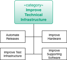
For an overview of other improvement practices, see Section 4.5, “Improvement Practices (Overview)”.
4.12. Practices to Improve Analyzability and Evaluability
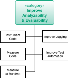
For an overview of other improvement practices, see Section 4.5, “Improvement Practices (Overview)”.
4.12.2. Docs-As-Code
Intent
Docs-As-Code is a documentation approach that raises developer-related documentation to the same importance as source code.
Description
Developer-related documentation of software systems is often neglected. In many situations, it’s not the lack of ideas for meaningful content that prevents documentation but the way developers have to do it: Separate programs have to be started and other work processes have to be followed. These and many more other distractions lead to long context switch times.
The additional effort could be a reason for a rather negative attitude towards documentation on the developer side. As a result, the developer’s documentation is neglected and becomes obsolete with the time until it can no longer be used for anything at all. Unfortunately, missing or outdated documentation has negative consequences for the understandability of the entire software system.
The core idea of Docs-As-Code is to use the same tools and processes for creating documentation as for creating source code. This ensures that there are no high costs for context switches.
There are a few practices that ensure that the acceptance of documentation increases in software development teams:
-
The documentation format is a simple, text-based format that can be opened and edited in any integrated development environment.
-
The necessary formatting of the texts can be done textually by a corresponding formatting syntax.
-
Diagrams can also be created with a pure text-based approach.
-
Changes to the texts are comparable to standard diffing tools.
-
The documentation is placed directly next to the source code in the same version control system.
-
The creation of the documentation artifacts (such as PDFs or HTML pages) that should be delivered is completely automated.
-
Automated tests check the structure and links within the document when documentation artifacts are created.
-
The same code review process and tooling is used for checking the documentation as well as for source code.
-
Documentation can be maintained in parallel for different versions and merged if required.
-
Optionally: The additional needed documentation is maintained in the same ticket system and implemented with the same processes as the implementation of new features for the software.
The seamless integration of documentation creation into the software development process means that there are no longer any obstacles for software developers to document necessary facts. By reusing the tools and processes, the documentation work gets the same importance as the writing of source code. Work on documentation becomes as visible as newly written code. The automated creation of documentation artifacts or websites makes the current status of the documentation more clear to other stakeholders such as product owners or project managers.
Experiences
When documentation and source code are in the very same code repository, developers can be kind of forced to update the documentation when they write new features or update existing ones. With the help of pull requests and code review techniques, it can be checked very quickly if necessary documentation updates were made.
Applicability
Apply this pattern when there is a clear lack of documentation. Start by defining the minimum required scope of documentation for new features (e. g. take some parts of the arc42 documentation template as a guidance if developers complain that they don’t know what to document).
Show the documentation in sprint reviews to make non-technical developers aware of the newly created content.
5. Cross-Cutting Practices and Patterns
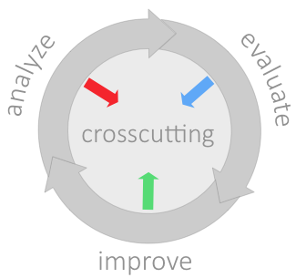
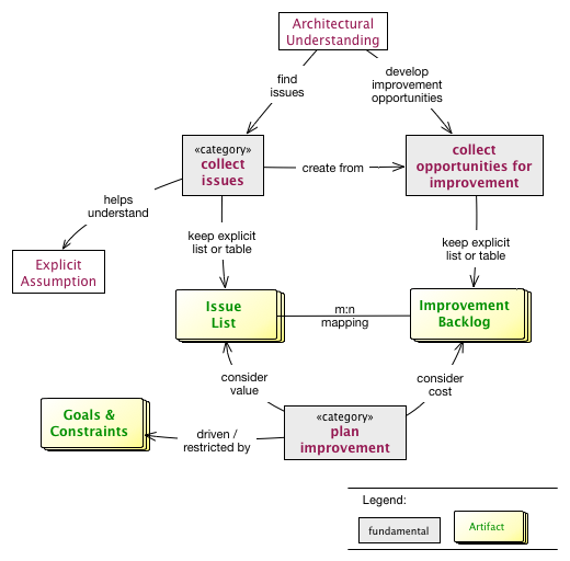
5.3. How it works
-
Start with collecting issues - mainly in Chapter 2, Analyze phase. Based upon your findings here, maintain an Section 5.15, “Issue List”
-
Evaluate those, determine values, preferably cost. This ensures you later solve important and relevant issues.
-
Section 5.6, “Collect Opportunities for Improvement” and evaluate those too.
-
Align issues and potential improvements, Section 5.16, “Plan Improvements”
-
Continously strive to increase your Section 5.5, “Architectural-Understanding”, as this facilitates identification of additional issues and improvements.
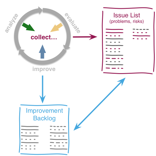
5.4. Cross-Cutting Practices
(given in alphabetical order)
-
Section 5.9, “Explicit Assumption” (work-in-progress: move to Fundamentals?)
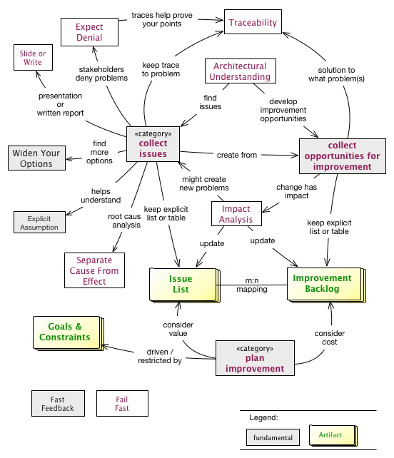
5.5. Architectural-Understanding
Develop and document an understanding of internal structures, concepts, architectural approaches and important decisions of the [System].
5.5.1. Description
Collect and organize architectural information about the [System]: Document structures, concepts, decisions, interfaces etc. of the [System] to locate issues, risks and opportunities for improvement.
-
Business or technical system context, with external interfaces. Learn this from Section 2.3.3, “Context-Analysis” or Section 2.3.8, “Infrastructure-Analysis”.
-
Solution strategy, often to be learnt from Section 2.3.24, “Stakeholder Interview” with experienced developers of the system.
-
Building block structure, the static organization of the source code. At least elaborate the highest level of code blocks (level 1 building blocks)
-
Runtime structures, like important use-case scenarios. Sometimes this can be learned from Section 2.3.21, “Runtime-Analysis”.
-
Infrastructure and deployment, often derived from Section 2.3.8, “Infrastructure-Analysis”.
-
Cross-cutting and technical concepts, like domain models, persistence, user-interface and other concepts.
-
Important architecture and design decisions taken and revoked during development of the system.
5.5.2. Experiences
Architectural understanding can be gained in small increments, so there is no need to reserve long times just for documentation.
Understanding should come from various sources - see all the Chapter 2, Analyze practices.
5.5.3. Related Practices
-
[arc42] provides a free and pragmatic template for software architecture documentation. It’s available in various formats (e.g. Microsoft-Word (tm) and AsciiDoc).
5.6. Collect Opportunities for Improvement
You should look for improvement opportunities, remedies, measures, tactics and strategies in all of the aim42-phases.
5.7. Collect Issues
You should constantly watch out for issues (problems and risks), especially during analysis activities like Section 2.3.24, “Stakeholder Interview” and others.
The artifact (physical collection) is the Section 5.15, “Issue List”.
Regularly match these issues to your collection of possible improvements.
5.8. Expect Denial
Some people will oppose your findings, will whitewash or sugarcoat issues, problems or root causes. Regardless on how careful you prepared your analysis, they will try to diminish, attack or dispute your findings.
5.8.1. Intent
-
Prepare you (as analyzer or evaluator or systems) for serious opposition and resistance by some stakeholders.
-
Describe which kind of reaction might be turned into acceptance.
-
Describe what might be gained by certain slightly negative reactions.
5.8.2. Description
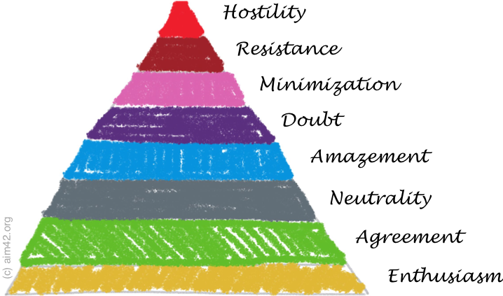
From enthusiasm to neutrality things will be easy, but from here on it gets interesting or difficult, however you might call it.
-
Enthusiasm: Some people will embrace your findings - like "that’s what we always said…". Enthusiasts sometimes expect that findings or the appropriate improvement approaches directly improve their own situation.
-
Agreement: Others will agree, without further ado.
-
Neutrality: Some stakeholders won’t care. These are probably unconcerned by any finding.
-
Amazement: Your results will amaze or astonish some people. Although they would never have expected your findings, amazed stakeholders might be convinced to agreement or neutrality by using explanation and proofs in stakeholder-specific language or communication. On the other hand, amazed stakeholders pose the serious risk of becoming more negative (doubtful or resisting) if you fail to convince them - or if other people (your opponents, for example) manage to bring them over to the dark side…
Always ask amazed stakeholders why for the reasons of their amazement - that can help you in your argumentation.
-
Doubt: You will hear or read "Can’t be, impossible!" or similar expressions from some people. If these stakeholders can explain the reasons for their doubts, you might find ways to improve your explanation (maybe your issues were simply ill-formulated) or you have to look for additional and better ways to explain. Doubt can lead you to errors or ommissions in your own argumentation or conclusions.
Some doubtful stakeholders will be emotional - and therefore not open for rational or objective arguments. That’s a serious and difficult communication problem - beyond the scope of this document.
-
Minimization, sometimes disavowal: This is the first level of denial. The fact itself is accepted, but its consequences, evaluations or seriousness are denied. In practice we encountered this phenomenon quite often: Affected stakeholders repeat their assessment "problem acknowledged, but the consequences are only minimal" like a mantra. Other stakeholders, especially doubtful or amazed ones, might start to believe in this minimization tactic - especially if the truth implies inconvenient or uncomfortable changes in their own working environment.
-
Resistance: Findings are opposed, either actively or passively.
In case you encounter minimization or resistance, get support from the highest management level you can access: As a consequence some, if not many, minimizing or resisting stakeholders will turn to your side.
-
Hostility, or "Shoot the messenger". Always remain calm and polite - but hard in your argumentation and facts. Hostile stakeholders can rarely be convinced of something, but need to be handled with diplomacy, politics and organizational skills (none of which we can cover here).
Be prepared for hostile actions, though: In case of critical issues, always keep details documentation of their origin. Be prepared to proof those issues, remove even minor omissions or formal weaknesses in your argumentation. Your issues and Section 2.3.20, “Root Cause Analysis” has to be flawless and backed by meticulous research and management support. Ensure Section 5.20, “Traceability” of your chain of reasoning! Keep written records of Section 2.3.24, “Stakeholder Interview” and of suspicious pieces of source code or documentation.
Let others review your findings before publication.
5.8.3. Experiences
In one audit of a European Logistic Company (> 40.000 employees) we found serious issues within their development processes, in addition to some issues in their source code. The process problems caused massive (> 3 months) delays in delivery of working software to production, whereas the pure software bugs were relatively minor in their consequences. When we presented these issues, all process-related issues were minimized or doubted by senior management of the IT department.
With the help of the CIO, we identified those minimizers to be the root cause of most process issues, as they had themselves introduced inefficient, formal and bloated processes.
5.8.4. Consequences
Especially when presenting results to (opposing) management stakeholders, you should be able to verify all your claims. In critical cases you should keep written protocols and note who-said-what in your stakeholder interviews.
5.9. Explicit Assumption
Compensate missing facts (especially requirements, goals, estimates, opinions) by explicit (written) assumptions about those facts.
5.9.1. Description
Making assumptions explicit is fundamentally important to Section 2.3.2, “Capture Quality Requirements”, so that development teams don’t need to rely on implicit assumptions or requirements.
When evaluating problems, risks or remedies, we often need to estimate or assume stuff like duration, cost, workload or others. These estimates or assumptions need to be made explicit, so that others can reproduce or understand our evaluation. In case of numerical estimation, it helps to apply Section 3.3.2, “Estimate in Interval”
Also known as educated guess.
5.10. Fail Fast
"fail fast" is actually a reference to an architecture principle describing a runtime behaviour of a system. I.e. if the application already knows that a remote system is not reachable, it should not try to send other/ more requests to this system so that this system can recover. Instead the application should immediately return either an error message or - even better - a functional fallback value.
Transferring this to software improvements, a fail-fast approach would be to immediately report when an improvement can not be applied. Don’t wait e.g. until the end of the sprint to communicate the failure. Instead this early feedback provides the opportunity to reflect and pivot on the improvement before the next sprint is started.
5.11. Fast Feedback
Fast Feedback is a well-known term which was e.g. coined in Bruce Tulgan’s book with the same name. Usually it’s about "frequent, accurate, specific and timely, and FAST feedback" in evaluation of different topics e.g. performance evaluation. Fast Feedback means that we don’t want to wait for six to twelve months until we get results or answers on a specific question. Instead we keep participants in a constant feedback loop so they immediately exchange information once they receive it.
The intention behind this is, the later a lack of quality is identified the higher the costs to fix it. Continuously evaluate the quality of work artifacts and immediately take countermeasures or pull the plug as early as possible. Similar to Section 5.10, “Fail Fast”.
Suitable methods to identify such situations are:
-
Code reviews
-
Architecture reviews
-
Peer reviews
-
Testing in early stages
See also Section 5.10, “Fail Fast”.
5.12. Impact Analysis
5.12.1. Intent
Determine what impact (in code, concepts, data and the organization) a specific action or issue (e.g. refactoring, recurring problem) will or might have. Identify the resultant effects on system development and operations.
5.12.2. Related Practices
-
Failure-Mode-and-Effect-Analysis (FMEA), a method for failure analysis, widely used in various industries
5.13. Goals and Constraints
5.13.1. Intent
Make the overall goals and constraints of the improvement efforts understandable to every stakeholder.
5.13.2. Description
It’s of the uttermost importance to clarify the expectations and assumption of all stakeholders of a software system. There may be conflicting interests or hidden doubts among the project’s participants that could let any improvement activity fail severely. Clear goals and understandable constraints are a great way to set the direction and the rules of the game.
Goals of improvements activities can be manifold. E. g. a goal could be to make sure that the software system gets more understandable. Another goal could be to be able to add new features or capabilities more easily in the future.
Goals are restricted by constraints. Because we live in a world with finite resources, we have to work with what we have in our (project) environment. E. g. constraints could be certain finish dates, organizational or technical limitations.
5.13.3. Representation
-
Quality scenarios are a good way to align business' goals with the actual technical requirements and constraints.
-
Architecture decisions contain information about goals and constraints that led to a certain decision.
-
Architecture Decision Records contain the problem statements (=goals) and the drivers (=constraints) that lead to a certain decision.
-
Impact Mapping is another nice methodology to trace goals (=Why?) over constraints (=How?) to the actual implementation (=What?).
5.13.4. References
-
Architecture decision in arc42: https://docs.arc42.org/section-9/
-
An introduction to Architectural Decision Records: https://adr.github.io/
-
Impact Mapping: https://www.impactmapping.org/
5.14. Improvement Backlog
Keep a public, written backlog of possible improvements, remedies, tactics or strategies.
-
Revise this backlog in regular intervalls.
-
Define the owner role for this backlog, similar to the product owner in Scrum.
-
Enhance the backlog with information from the Chapter 3, Evaluate phase, like cost, effort or risk.
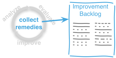
5.14.1. Intent
Collect all known issues and problems within a system or its associated processes. Make the issues comparable by evaluating each one, usually using economical units like money or time. Align carefully with Section 5.15, “Issue List”.
5.14.2. Content
| ID | Improvement | Description | min Cost | max Cost | Related Issues |
|---|---|---|---|---|---|
identifier |
name |
short description of this improvement or remedy |
minimal estimated cost or effort |
maximal cost or effort |
links to related issues |
5.14.3. Representation and Tools
Try to use a similar documentation approach like for Section 5.15, “Issue List”. It should be as easy as possible to link issues to improvements and vice versa.
5.15. Issue List
A collection of issues (problems, risks) found during Section 5.7, “Collect Issues”.
5.15.1. Intent
Collect all known issues and problems within a system or its associated processes. Make the issues comparable by evaluating each one, usually using economical units like money or time.
5.15.2. Content
| ID | Issue | Description | Frequency | min Value | max Value | Improvements |
|---|---|---|---|---|---|---|
identifier |
name |
a short description of the issue |
how often does the issue occur, once, daily, weekly, with every new feature? |
minimal value |
maximal value |
links to improvements |
5.15.3. Representation and Tools
It’s difficult to decide how much formalism to apply in collecting issues and problems: Sometimes a wiki page might suffice, for other systems a full-blown issue tracker can be useful.
As always: documentation is only valuable if it can be found easily, which makes electronic approaches more viable.
For every entry in this issue list we need to Section 3.3.3, “Estimate Issue Cost”, an estimation of the cost of this issued in any business-related unit.
In case you already have identified or developed opportunities for improvement adressing this issue, links to the corresponding improvements (remedies, tactics, strategies, changes) in the Section 5.14, “Improvement Backlog” are neccesssary.
5.16. Plan Improvements
Conduct long- and short-term planning of improvement activities. Balance or align issues and improvements, considering existing goals and constraints.
Consists of long-term decisions (concerning Section 4.4, “Improvement Approaches (Overview)”) and short-term planning.
5.17. Report-Structure
When you examine (audit, review) systems, as proposed in Chapter 2, Analyze, you often need to prepare a report for the management in charge.
This practice proposes a generic report structure you might use in preparing such documents.
| Chapter | Description |
|---|---|
Formalities |
formal stuff, like disclaimer, references to contractual documents, table of contents, licence, change history etc. |
Management Summary |
1, at most 2 page summary |
Goals |
describe the goals of the review/audit. |
Review Approach |
brief description how the review was conducted, outline the activities or actions performed. |
Stakeholders |
outline which stakeholders participated, in what form, at that time |
Findings |
in order of importance or priority, list and explain your findings |
Proposed Actions |
|
Conclusion |
|
Appendix: Sources |
list your sources and references, e.g. documents, source-code, interview protocols, issue-trackers, websites etc. |
Appendix: The Team |
briefly introduce the review team and explain their role in the review. |
5.17.1. Related Practices
-
Section 5.19, “Slide or Write” to decide, wether you really need to prepare a written report.
-
Section 5.20, “Traceability”, to ensure you have proper sources for all important issues.
5.18. Separate-Cause-From-Effect
5.18.1. Intent
Explicitly differentiate between symptom (effect) and cause:
-
Identify root causes of symptoms, problems or issues
-
Trace a problem to its origins
5.19. Slide or Write
In every review you will face the question of how to deliver and present the results to the customer. Will you write a long and formal report document or is a set of presentation slides adequate and sufficient?
5.19.1. Intent
-
Consider format and structure of the review report early.
-
Ensure that you share a common vision with your customer about the preparation of results .
-
Remind contractual agreements and formal requirements, especially if someone might take offence by your report.
5.19.2. Description
There are two common ways to deliver review results:
-
As a formal document (Word, PDF, etc.)
-
As a collection of slides (PowerPoint, Keynote, etc.) and a presentation
In general it is recommended to write the review results down in a well-structured document. This form is suitable to contain a lot of details and background information, so that it is easy e.g. to trace back a recommendation to a stakeholder interview. A written document can (and should) contain all information needed to understand the review starting position, targets, approach and findings, without spoken words and additional explanations. If the results shall supplementary be presented to some audiences it is easy to create purposeful slides from this document.
A set of PowerPoint slides as only result is adequate if the customer has been closely involved in the review process and is mainly interested in the outcome and if there will definitely be a presentation given to all relevant stakeholders. In this case the creation of slides with the most important bullet points might be quicker than the writing of detailed, well formulated text.
5.19.3. Experiences
In a review for a financial broker we agreed initially to deliver a detailed document with the results. When we were later asked to present the outcomes to two different audiences (engineers and management) it was quite easy to create specific slides for both of them from the ~ 40 pages of documentation.
In another case we planned to present out review finding in one big meeting and so we wrapped all findings into briefly and concise slides. Later some executives who missed the meeting complained that they needed some spoken explanations to understand the presentation document. We spent much more time in subsequently writing out the background information as if we had worked on a result document from beginning on.
5.20. Traceability
Maintain references to the origin of problems or issues: Remember who told you about a problem, in which documents you found issues and in what version of the source you identified risks or faults.
5.20.1. Intent
When discussing problems, some stakeholders will question or doubt your findings (see pattern Section 5.8, “Expect Denial”). Keeping thorough references to the origins or original sources of major findings keep eventual critics in check.
5.20.3. Experiences
Some contrary experiences happened when we neglected traceability:
Stakeholder questioned some of our findings - we could not immediately trace those findings back to an original source (i.e. an interview protocol, a particular file/version of source code). These stakeholders immediately suspected all our findings, not only the one or two in question.
Please keep in mind that a lack of traceability, especially for disputed findings or problems, might lead to serious loss of credibility.
On the other hand, maintaining detailed references is a time-consuming task. You easily spend hours with (rather trivial) bookkeeping activities, instead of identifying new and exciting problems.
5.20.4. Applicability
Apply traceability whenever you identify problems or issues
-
which might discredit or offend one important stakeholder,
-
which seriously impact parts of the underlying organization, company or business unit,
-
that carry huge financial, technical or organizational risks or penalties.
Short rule: The more expensive or dangerous, the more traceability you need.
5.21. Widen Your Options
Before taking decisions it’s often a good idea to widen your decision space, look for additional options. Sometimes it’s not only "yes-or-no" decisions, but a spectrum of additional options are available - at least if you allow your brain to deviate from conventional path or your own preliminary conclusions.
6. Pattern index
This chapter contains an alphabetic list of all patterns, practices and methods with a short description and links to the explanation.
-
Section 4.10.2, “Anticorruption Layer”
Isolate clients from internal changes of sub-systems or modules. Category: Chapter 4, Improve
-
Section 5.5, “Architectural-Understanding”
Document relevant structures, concepts, decisions, interfaces etc. of the [System] to locate issues, risks and opportunities for improvement. See [arc42] and Section 2.3.28, “View Based Understanding”. Category: Chapter 5, Cross-Cutting Practices and Patterns
-
- Architecture-Backlog
-
Keep a prioritized list of improvement tasks (remedies) with their as a backlog, parallel to the (regular) feature backlog. Category: Chapter 4, Improve
-
- Assertions
-
Use assertions to verify preconditions and to make a program fail early when something goes fundamentally wrong. Category: Chapter 4, Improve
-
Systematic approach to find architectural risks, tradeoffs (compromises) and sensitivity points. Category: Chapter 2, Analyze
-
- Automated Tests
-
Introduce automated tests to verify correctness or runtime behavior. Unit-, integration-, acceptance-, load- or database-tests are well-known specialisations of this. Category: Chapter 4, Improve
-
Section 4.7.1, “Big Bang Approach”
Approach to replace an old system with a new system with one big bang deployment. Category: Chapter 4, Improve
-
- Branch For Improvement
-
Introduce distinct branches in your version control system to reflect improvements. Category: Chapter 4, Improve
-
- Bulkhead
-
Can be placed between two systems to avoid the propagation of faults from one system to the other system ([Nygard07], p. 119ff.). Category: Chapter 4, Improve
-
Section 2.3.2, “Capture Quality Requirements”
Part of Section 2.3.1, “Atam”, Capture and document specific quality requirements. Specialisation of Section 2.3.19, “Requirements-Analysis”. Category: Chapter 2, Analyze
-
- Change by Extension
-
Enable efficient change by creating new components instead of modifying existing ones. Category: Chapter 4, Improve
-
- Change by Copy
-
Isolate competing change necessity by copying and allowing the copies to evolve independently. Also known as [Change-Via-Split] Category: Chapter 4, Improve
-
- Change Via Split
-
Isolate competing change necessity by copying and allowing the copies to evolve independently. Also known as [Change-Via-Split] Category: Chapter 4, Improve
-
Section 5.6, “Collect Opportunities for Improvement”
Keep a list of possible and potential measures, remedies, tactics, strategies for improvements. Regularly match those to your collection of issues. Category: Chapter 5, Cross-Cutting Practices and Patterns
-
Keep a list of problems, issues and risks. Regularly match those to your collection of possible remedies. Category: Chapter 5, Cross-Cutting Practices and Patterns
-
Section 2.3.3, “Context-Analysis”
Analyse external interfaces for risk, technology, business value and other factors. Category: Chapter 2, Analyze
-
Section 2.3.4, “Data-Analysis”
Analyse and inspect the data created and manipulated by the system for its content, structure, quantity and size. Category: Chapter 2, Analyze
-
Identify the source of a bug or misbehavior by observing the detailed flow of execution, e.g. stepwise execution of program statements. Usually supported by debugger. Specialisation of Section 2.3.20, “Root Cause Analysis”. Category: Chapter 2, Analyze
-
- Deprecate Obsolete Parts
-
Actively mark parts in software that aren’t needed anymore and communicate to your consumers or customers, that you will remove specific functionality in the future. Category: Chapter 4, Improve
-
Section 2.3.6, “Development-Process-Analysis”
Analyse and inspect the development process (as documented or described by stakeholders) for appropriateness, problems or problem-areas. Category: Chapter 2, Analyze
-
Section 2.3.7, “Documentation-Analysis”
Analyse existing documentation for availability, correctness, actuality, problems or problem-areas. Category: Chapter 2, Analyze
-
- Document Problems
-
See Improvement Backlog. Category: Chapter 5, Cross-Cutting Practices and Patterns
-
Section 3.3.1, “Estimate Feature Value”
Estimate the (monetary) value of a given feature, so you can compare features of the system with each other. Category: Chapter 3, Evaluate
-
Section 3.3.2, “Estimate in Interval”
Estimation differs from measurement in its inherent uncertainty. Therefore, estimate in intervals, giving lower and upper bounds. The difference between the two shows your confidence in the estimate. Low (relative) difference means high confidence. Category: Chapter 3, Evaluate
-
Section 3.3.3, “Estimate Issue Cost”
Find out how much a given issue costs in units of money or effort in a period of time or for every occurence. Category: Chapter 3, Evaluate
-
Section 3.3.4, “Estimate Improvement Cost”
Determine how much a specific improvement (a set of actions taken to eliminate or reduce a specific issue or problem) is likely to cost (in money and/or effort). Category: Chapter 3, Evaluate
-
Some people will oppose your findings, will whitewash or sugarcoat issues, problems or root causes. Regardless on how careful you prepared your analysis, they will try to diminish or attack your findings. Category: Chapter 5, Cross-Cutting Practices and Patterns
-
Section 5.9, “Explicit Assumption”
Compensate missing facts (especially requirements, goals, estimates, opinions) by explicit (usually written) assumptions about those facts. Category: Chapter 5, Cross-Cutting Practices and Patterns
-
- Extract Reusable Component
-
Extract code from an existing system to create a reusable component. See [SERIOUS-Refactoring], page 95. Category: Chapter 4, Improve
-
Identify quality issues as early as possible and aim to fix them. Category: Chapter 5, Cross-Cutting Practices and Patterns
-
Evaluate the quality of work artifacts and processes as early as possible. Enables teams to apply corrective actions or take countermeasures as early as possible. Category: Chapter 5, Cross-Cutting Practices and Patterns
-
- Front End Switch
-
Route front-end requests to either new or old backend systems, depending on their nature, content-negotiation or other request criteria. This is especially helpful to support [Never-Change-Running-System]. Category: Chapter 4, Improve
-
- Group Improvement Actions
-
Collect several improvement actions, which can or shall be applied or implemented together. Category: Chapter 4, Improve
-
- Handle If Else Chains
-
Refactor nested if-then-else structures for improved understandability. Can be seen as a specialisation of [Remove-Nested-Control-Structures]. Category: Chapter 4, Improve
-
Section 2.3.9, “Hierarchical-Quality-Model”
Decompose the overall goal of "high quality" into more detailed and precise requirements, finally resulting in a tree-like structure. See Section 2.3.1, “Atam” and [Quality-Requirements]. Category: Chapter 2, Analyze
-
Section 5.12, “Impact Analysis”
Determine what impact (in code, concepts and the organization) a specific action (e.g. refactoring) will or might have. Category: Chapter 5, Cross-Cutting Practices and Patterns
-
- Improve Code Layout
-
Making code easier to read results in better understandability. Category: Chapter 4, Improve
-
Section 4.10.4, “Improve Logging”
Making runtime analysis easier with meaningful logs. This includes decentralized log analysis as well as well-structured log levels, markers and log message phrasing. Category: Chapter 4, Improve
-
Section 5.14, “Improvement Backlog”
Keep a backlog of possible improvements, remedies, tactics or strategies. Category: Chapter 5, Cross-Cutting Practices and Patterns
-
Section 2.3.8, “Infrastructure-Analysis”
Analyze the technical infrastructure of the [System], e.g. with respect to time and resource consumption or creation. Part of Section 2.3.21, “Runtime-Analysis”. Category: Chapter 2, Analyze
-
Section 2.3.10, “Instrument System”
Instrument either the executable or the source code to make assumtions explicit and expand on Section 2.3.21, “Runtime-Analysis” and [Runtime-Artifact-Analysis]. Category: Chapter 2, Analyze
-
Section 4.10.5, “Interface Segregation Principle”
Reduce coupling between clients and service provider. Category: Chapter 4, Improve
-
Section 4.10.6, “Introduce Boy Scout Rule”
Establish a policy to perform certain structural improvements each time an artifact (source code, configuration, documents etc.) is changed. Usable in situations where a [Refactoring-Plan] is not feasible or in addition to such a plan. Category: Chapter 4, Improve
-
- Introduce Layering
-
Introduce layers within the source code to improve separation of concern. It’s common to have at least a business layer and an interface layer - the latter for both user- and programatic interfaces. See Uncle Bob’s Clean Architecture for a short summary. Category: Chapter 4, Improve
-
- Isolate Changes
-
Introduce interfaces and intra-system borders, so that changes cannot propagate to other areas. Category: Chapter 4, Improve
-
Keep a list or collection or issues (problems, risks) - together with an appropriate amount of description and evaluation. Category: Chapter 5, Cross-Cutting Practices and Patterns
-
Section 2.3.11, “Issue-Tracker-Analysis”
Analyse entries from issue-tracker to identify critical areas, components or stakeholders. Category: Chapter 2, Analyze
-
- Keep Data Toss Code
-
A strategy to improve systems, keeping the data created with the (old) systems as foundation for a new one. Also described as Bridge-to-the-New-Town (by Wolfgang Keller). This is the opposite of [Never-Change-Running-System]. Category: Chapter 4, Improve
-
Section 4.10.7, “Manage Complex Client Dependencies With Facade”
Simplify the interaction of a client with a set of service components. Category: Chapter 4, Improve
-
Gather various metrics and visualize them on dashboards in order to make your system behavior more predictable and assumed coincidences explainable. Examples of such metrics are thread pool saturation, number of failed logins, requests per second but also number of successful orders today, amount-of-time-spent-debugging-this-component, code-metrics, amount-of-effort-needed-for-feature… Category: Chapter 4, Improve
-
- Migrate Data
-
Transform existing data from one structure or representation into another by keeping its original intent or semantic intact. Category: Chapter 4, Improve
-
- Mikado-Method
-
Coordinated refactoring effort, described in the Mikado-book. Category: Chapter 4, Improve
-
- Natural Death
-
Keep old system running and only retire it once all objects contained reach end of life according to their life cycle. Category: Chapter 4, Improve
-
- Never Change Running System
-
To minimize risks, you should try to refrain from changes to existing (working) code - as every change inevitably introduces new risks or even bugs. Category: Chapter 4, Improve
-
- Never Rewrite Running System
-
Joel Spolsky arguments, never to rewrite a system from scratch, as you will likely make many new mistake and won’t generate much added value. Category: Chapter 4, Improve
-
Section 2.3.12, “Organizational-Analysis”
Analyse and inspect organization(s) responsible for the system. Category: Chapter 2, Analyze
-
- Outside-in Interfaces
-
Modularize system aligned to (existing) external interfaces. Category: Chapter 4, Improve
-
Section 2.3.16, “Pre Interview Questionnaire”
Prior to interviewing stakeholders, present them with a written questionnaire, so they can reflect in advance. A specialisation of Section 2.3.18, “Questionnaire”. Category: Chapter 2, Analyze
-
Identify issues that could let become the current project a huge disaster. Category: Chapter 2, Analyze
-
Section 2.3.14, “Qualitative Analysis”
Analyze which quality goals of the [System] are at risk and which are met by the current implementation. Needs concrete [Quality-Requirements]. See Section 2.3.1, “Atam”. Category: Chapter 2, Analyze
-
- Quality Driven Software Architecture (QDSA)
-
Derive (technical, structural or process-related) decisions based upon detailed quality requirements. QDSA requires explicit quality requirements. Category: Chapter 4, Improve
-
Section 2.3.15, “Quantitative-Analysis”
Measure artifacts or processes within the system, e.g. source code. For example, see Section 2.3.21, “Runtime-Analysis” and Section 2.3.25, “Static Code Analysis”. Category: Chapter 2, Analyze
-
Section 2.3.18, “Questionnaire”
Written collection of questions presented to stakeholders. Can be addendum, preparation or replacement of Section 2.3.24, “Stakeholder Interview”. Category: Chapter 2, Analyze
-
- Refactoring
-
Source code transformation that does not change functionality of system. See [Fowler-Refactoring]. Category: Chapter 4, Improve
-
- Refactoring Plan
-
The route of refactoring, as discussed within the development team. This plan should always be visible to every team member. Category: Chapter 4, Improve
-
Section 2.3.19, “Requirements-Analysis”
Analyze and document (current) requirements: required features and required constraints Category: Chapter 2, Analyze
-
- Remove Nested Control Structures
-
Re-structure code so that deeply nested or complicated control structures are replaced by semantically identical versions. Special case of [Refactoring], similar to [Untangle-Code]. Often performed by reducing complexity and especially cyclomatic complexity. When reducing code complexity one needs to make sure we’re not exchanging inner/ method/ cyclomatic complexity by outer/ design or runtime complexity. Category: Chapter 4, Improve
-
Section 5.17, “Report-Structure”
A generic structure for written audit or review reports, usually following an Chapter 2, Analyze phase. See Section 5.19, “Slide or Write”. Category: Chapter 5, Cross-Cutting Practices and Patterns.
-
Section 2.3.20, “Root Cause Analysis”
Find the evil at the bottom: Explicitely differentiate between symptom and cause: Identify root causes of symptoms, problems or issues. Category: Chapter 2, Analyze
-
Section 2.3.21, “Runtime-Analysis”
Analyze the runtime behavior of the [System], e.g. with respect to time and resource consumption or creation. Category: Chapter 2, Analyze
-
- Runtime Artifact Analysis
-
Artifacts that were created by a running system are a gold mine. They allow you to get a deeper understanding of the inner workings of a software system. Use log management, aggregators and monitoring tools to gather log files. Then analyze usage patterns, stack traces or errors to see what the system is really doing. Category: Chapter 2, Analyze
-
- Sample For Improvement
-
Provide concrete code example for typical improvement situations, so that developers can improve existing code easily. Category: Chapter 4, Improve
-
- Schedule Work
-
Schedule refactoring or improvement work, so that all (business and technical) stakeholders know about them. Category: Chapter 4, Improve
-
Section 2.3.22, “Software Archeology”
Understand software by analysing its source code, usually in absence of other documentation or knowledge sources. Category: Chapter 2, Analyze
-
Section 2.3.23, “Stakeholder Analysis”
Find out which people, roles, organizational units or organizations have interests in the [System]. Category: Chapter 2, Analyze
-
Section 2.3.24, “Stakeholder Interview”
Conduct personal interviews with key persons of the [System] or associated processes to identify, clarify or discuss potential issues and remedies. Category: Chapter 2, Analyze
-
- Stakeholder Specific Communication
-
Communicate with stakeholders by actively applying their specific or favored terminology and/or communication channels. Category: Chapter 5, Cross-Cutting Practices and Patterns
-
Section 2.3.25, “Static Code Analysis”
Analyse source code to identify building blocks and their dependencies, determine complexity, coupling, cohesion and other structural properties. Category: Chapter 2, Analyze
-
Section 4.7.8, “Strangler Approach”
Approach to gradually create a new system around the edges of the old, letting it grow slowly over several years until the old system is strangled. Category: Chapter 4, Improve
-
- Structural Analysis
-
Analyze the static structures (e.g. building block structure) of the [System], e.g. package or module dependencies, runtime- and/or deployment dependencies. See the more specific Section 2.3.25, “Static Code Analysis”, Section 2.3.3, “Context-Analysis” and Section 2.3.4, “Data-Analysis”. Category: Chapter 2, Analyze
-
- Systematic Decisions
-
Systematically prepare and take decisions by finding appropriate options, check assumptions, overcome emotion and prepare to be wrong. See Decisive (by C+D Heath). Category: Chapter 5, Cross-Cutting Practices and Patterns
-
Section 2.3.26, “Take What They Mean, Not What They Say”
Natural language has the risk, that semantics on the senders' side differs from semantics of the receiver: People simply misunderstand each other because meaning of words differ between people. Pattern provided by Phillip Ghadir (who is too humble to claim this discovery) Category: Chapter 2, Analyze
-
- Toggle Feature
-
Simultaneously support evolved, competing or conflicting features at runtime by toggling feature flags. Category: Chapter 4, Improve, see also:
-
Maintain references to the origin of problems or issues: Remember who told you about a problem, in which documents you found issues and in what version of the source you identified risks or faults. Category: Chapter 5, Cross-Cutting Practices and Patterns
-
- Untangle Code
-
Remove unneccessary complications in code, e.g. nested structures, dependencies, dead-code, duplicate-code etc. See [Remove-Nested-Control-Structures]. Special case of [Refactoring]. Category: Chapter 4, Improve
-
- Use Case Cluster
-
Understand system functionality by grouping functionality into clusters to reduce complexity. Category: Chapter 2, Analyze
-
Section 2.3.27, “User-Analysis”
Get an overview of user-categories or -groups, their goals, requirements and expectations. Find out about issues users have with the system. Related to Section 2.3.23, “Stakeholder Analysis”, Section 2.3.3, “Context-Analysis” and Section 2.3.19, “Requirements-Analysis”. Category: Chapter 2, Analyze
-
Section 4.10.9, “Use Invariants To Kill Zombies”
Use Invariants to make sure that you can kill Zombies safely. If code seems to be “dead” — meaning that it supposedly isn’t called anymore — but no one dares to remove it from the codebase, the introduction of invariants can provide reliable feedback on whether it is safe to remove the code or not. Category: Chapter 4, Improve
-
Section 2.3.28, “View Based Understanding”
Create architectural views (mainly building block view) to understand and communicate code structure. Category: Chapter 2, Analyze
Appendix A: Domain Model
Within the systematic improvement we consider and manipulate several typical kinds of information, entities.
For a more pragmatic description, please see the Section 1.4.2, “Common Terminology” section
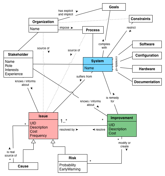
Cause |
Root cause of an Issue, in contrast to a symptom. |
|
is-a |
(inherits from) Issue |
|
is real source of |
one or many Issues. |
|
Configuration |
||
Constraints |
Technical or organizational constraints, restraining management, design, implementation or operation of the System. |
|
restrict |
the System, associated Processes or Organization. |
|
Documentation |
Any (hopefully written) information about the systems, its goals, requirements, architecture, implementation, operation or management. |
|
Goals |
What does the Organization or Stakeholder expect from the System, why does the System exist anyway. |
|
Hardware |
Structure and kind of hardware required to develop, test and operate the System. |
|
Improvement |
Any remedy, opportunity, tactic or strategy to improve the System by resolving one or several Issues. |
|
modifies or creates |
Risk |
|
is remedy for |
the System. |
|
resolves |
(partially or complete) one or several Issues |
|
Issue |
Any problem, error, fault, risk, suboptimal situation or their causes within the System, Processes or Organization related to it (e.g. management, operational, development, administrative or organizational activities). |
|
Frequency: |
how often does the Issue occur? |
|
resolved by |
one or several Improvements. |
|
Organization |
The organization or entity responsible or owning the System. |
|
source of |
Issues. |
|
Process |
Processes, conventions or activities for developing, maintaining, operating or managing the System. |
|
source of |
Issues. |
|
Risk |
||
EarlyWarning |
Indicator that the Risk is occuring and turning into a problem. |
|
is an |
(inherits from) Issue, but not occurred yet. |
|
Software |
All source code and configuration that make up the System under improvement. Hopefully stored in version-control. |
|
is an |
Issue, but not occurred yet. |
|
Stakeholder |
People or roles interested or participating in the System or any of its associated Processes. |
|
belong to |
the Organization responsible or owning the System. |
|
knows / informs about |
Issues and/or Improvements. Stakeholders often know about existing problems and opportunities for improvements. |
|
System |
The system under improvement, consisting of Software, Hardware and Documentation. |
|
managed and affected by |
Processes |
|
remedy |
the System or aspects of it by Improvements |
|
suffers from |
Issue |
|
complies with |
one or several Goals. |
|
consists of |
Software, Configuration, Hardware and Documentation. |
|
Appendix B: Bibliography
-
[arc42] arc42: Resources for Software Architects. Practical template, liberal licence. Available in a variety of formats, see German website or English website.
-
[Agans-Debugging] David J. Agans: Debugging: The 9 Indispensable Rules for Finding Even the Mose Elusive Software and Hardware Problems. Amacom Press, 2002. Although most developers take "debugging skills" for granted, they sometimes spend too much time tracking too little bugs.
-
[Ambler] Scott Ambler on Database Refactoring: http://agiledata.org/essays/databaseRefactoring.html
-
[Annett-Legacy] Robert Annett: Working with Legacy Systems: A practical guide to the real systems we inherit. Leanpub Publishing.
-
[Brown] William J. Brown: AntiPatterns: Refactoring Software, Architecture and Projects in Crisis, John Wiley & Sons, 1998 — a tried and true work on things that tend to go wrong in software development and other projects.
-
[Berglung-AfferentCoupling] Tim Berglund (GitHub) on Complexity Theory and Software Development. Look at slide 73ff on afferent coupling - and keep that in mind for your own refactorings.
-
[Bass09] Len Bass et.al.: Software Architecture in Practice. Addison-Wesley, 2. Edition 2009.
-
[Big-Ball-Of-Mud] Brian Foote and Joseph Yoder, Big Ball of Mud - very influentual paper from the fourth conference on Patterns languages of Program Design, PLoP97
-
[BISBAL] BISBAL, J. et.al.: A Survey of Research into Legacy System Migration. Technical Report TCD-CS-1997-01, Computer Science Department, Trinity College Dublin, 1997. http://citeseerx.ist.psu.edu/viewdoc/summary?doi=10.1.1.50.9051
-
[Bommer-Wartung] Christoph Bommer, M. Spindler, V. Barr: Softwarewartung: Grundlagen, Management und Wartungstechniken. (in German) dpunkt Verlag, 2008. Interesting treatment of categories of software systems and their respective need for maintenance and evolution. Authors quote studies from Lehman and Belady from the 1970’s.
-
[Boy-Scout-Rule-article] The Boy Scout Rule, see http://programmer.97things.oreilly.com/wiki/index.php/The_Boy_Scout_Rule
-
[Brodie-Stonebraker] Brodie, M. and Stonebraker, M: Migrating Legacy Systems: Gateway, Interfaces & the Incremental Approach; Morgan Kaufmann 1995.
-
[Clements-ATAM] Paul Clements et.al.: Evaluating Software Architecture - Methods and Case Studies. Addison-Wesley, 2001. Detailed overview of ATAM (and other evaluation methods).
-
[Campbell14] Ann Campbell et. al: SonarQube in Action. Manning Publications, 2014. Great introduction to the flexible, multi-language code-analysis toolkit.
-
[ERDLE] ERDLE, C.: Management von Softwaresystemen – Legacy Migrationsstrategien. Seminar an der TU München, Fakultät Informatik, 2005. http://www4.in.tum.de/lehre/seminare/hs/WS0506/mvs/files/Ausarbeitung_Erdle.pdf
-
[Evans03] Eric Evans: Domain-Driven Design: Tackling Complexity in the Heart of Software. Addison-Wesley, 2003.
-
[Feathers] Michael Feathers: Working Effectively with Legacy Code. Prentice Hall, 2005. The author claims "Code without tests is bad code". So true…
-
[Fowler-Refactoring] Martin Fowler: Refactoring. Addision-Wesley. Addision-Wesley, 1999. See also refactoring.com
-
[Freemann] Steve Freeman, Nat Pryce: Growing Object Oriented Software By Tests. Addison-Wesley, 2010.
-
[heath-decisive] Chip and Dan Heath: Decisive: How to make better choices in life and work. Crown Publishing / Random House Books, 2013. A practical and pragmatic guide to decision making (both preparing and taking them) - not specific to software. They describe four pillars of systematic decision making, which we adopted for our cross-cutting practice Systematic-Decisions.
-
[Henney] Kevlin Henney: 97 Things Every Programmer Should Know. O’Reilly Media, 2010, ISBN 0596809484, also available online
-
[Hunt-Archeology] Andy Hunt, Dave Thomas: Software Archeology, IEEE Software, March/April 2002
-
[Impact-Mapping] Gojko Adzic: Impact Mapping. Making a Big Impact With Software Products and Projects.
-
[ISO-9126] ISO 9126 Quality Model: Hierarchical model for software quality, consisting of six major quality topics (functionality, reliability, usability, efficiency, maintainability and portability).
-
[ISO-14764] ISO/IEC 14764 Standard on Software Maintenance:2006. For a brief overview, see Wikepedia-entry on ISO-14764.
-
[ISO-25010] ISO/IEC 25010 Systems and software Quality Requirements and Evaluation (SQuaRE) — System and software quality models. ISO-Standard model for software quality. Superseeds [ISO-9126] and categorizes software quality into 8 characteristics: functional suitability, reliability, efficiency, operability, security, compatibility, maintainability, transferability. See ISO-25010 website.
-
[Keller-Migration] Wolfgang Keller: The Bridge to the New Town - A Legacy System Migration Pattern. EuroPLoP 2000, ISBN 3-87940-775-4
-
[Lippert-Refactoring] M.Lippert, S.Roock: Refactoring in Large Software Projects: Performing Complex Restructurings Successfully, Wiley 2006
-
[Martin-CleanCode] Robert Martin: Clean Code - A Handbook of Agile Software Craftmanship. Prentice Hall, 2009. A detailed writeup of how (object-oriented) code should look like. Lots of things we like.
-
[Mikado] Ola Elnestam, Daniel Brolund: The Mikado Method. Manning, 2014. Describes a method to morphing software from bad to better state. Quote from the book: “It helps us visualize, plan, and perform business-value-focused improvements over several iterations and increments of work, without ever having a broken codebase”
-
[Moyer-Archeology] Brian Moyer: Software Archeology
-
[Nygard07] Michael T. Nygard: Release It! Design and Deploy Production-Ready Software. Pragmatic Programmers, 2007.
-
[Object-Oriented-Software-Construction] Bertrand Meyer: Object-Oriented Software Construction, Prentice Hall (September 1994), ISBN-13: 978-0136290490
One of those old books which is has influenced many a software but is actually known to few. -
[Ogawa-Evolution] Michael Ogawa: Software Evolution Storylines. Available as research paper, open-source code and online. Visualizes interactions between developers in software systems
-
[OORP] Serge Demeyer et. al: Object-Oriented Reengineering Patterns. A pattern-based approach to re-engineer object-oriented legacy systems. It contains a wealth of improvement-patterns, some named slightly different than their aim42-brethren.
-
[Quality-Requirements] (Free) Examples of Practical Software Quality Requirements.
-
Sadalage, P.: Refactoring Databases: Evolutionary Database Design. Collection of patterns for database refactoring. Online: http://databaserefactoring.com/
-
[SEI-ATAM] Architecture Tradeoff Analysis Method. Software Engineering Institute, Carnegie Mellon University.
-
[SERIOUS] Software Evolution, Refactoring, Improvement of Operational & Usable Systems. ITEA / EUREKA research project. Completed in 2008, holds a fairly large number of deliverables. Too bad, some of the result websites are down…
-
[SERIOUS-Refactoring] SERIOUS Refactoring Handbook.
-
[SERIOUS-Methods] SERIOUS project. Overview and evaluation of design and refactoring methods
-
[Software-Evolution] Journal of Software: Evolution and Process. Academic journal on software evolution and maintenance.
-
[SonarQube] SonarQube is an free and open platform to measure manage code quality, lots of plugins for a variety of programming languages, plugins for different metrics and checks. SonarQube can track results over time - showing the history of code quality for software systems.
-
[Spolsky-NeverRewrite] Joel Spolsky: Things You Should Never Do, Part-I
-
[Tornhill-CrimeScene] Adam Tornhill: Your Code as a Crime Scene. Use forensic techniques to arrest defects, bottlenecks and bad design in your programs. Pragmatic Programmers, 2015. Despite the seemingly funny title, this is one of the most practical books on analyzing source code from arbitrary languages. The author has implemented several of the ideas as open-source tools.
-
[Tornhill-XRay] Adam Tornhill: Software Design X-Rays: Fix Technical Debt with Behavioral Code Analysis. Pragmatic Programmers, 2018. This book focuses on the social behavior of software developers. It shows how you can spot knowledge loss, hidden change dependencies and hot spots of bad code.
Appendix C: Glossary
- AIM42
-
Architecture Improvement Method.
- ATAM
-
Architecture Tradeoff Analysis Method. Extensively described in Clemens-2001 and online by the SEI, briefly described as aim42 pattern.
- Failure
-
Loss of functionality under defined (stated) conditions.
- Issue
- Remedy
- SEI
-
Software Engineering Institute at the Carnegie Mellon University. A federally funded research and development institute, sponsored by the US Departement of Defense.
- System
-
The system to be improved - often a single software system, but it might be a complex combination of hardware, software and organizational aspects. Systems in our sense consists of:
-
software, usually with corresponding data structures and data
-
required infrastructure software, like operating system, database, UI-frameworks, middleware etc.
-
required hardware infrastructure, like processors, storage facilities, network, routers etc.
-
associated development processes, like requirements engineering, architecture, implementation, version- and configuration management, build- and deployment
-
associated administration and operation processes or procedures
-
associated organizational processes, like budgeting, HR, controlling, management etc.
-
associated external systems, like data-/event providers or consumers.
-
and maybe even more :-)
- Value
-
(of an improvement or remedy). Approximately -1 times the cost of the associated issue(s). If an improvement solves only part of an issue, value estimation becomes much harder.
Appendix D: Organizational Stuff
The Team
For a current and complete overview, please see the contributor page on Github.
-
Gernot Starke (innoQ Fellow, project founder): setup, patterns, practices, maintenance.
-
Alex Heusingfeld (innoQ): hero-of-the-build, Travis-CI integration, numerous discussions. Started the idea of a distinct user guide…
-
Peter Hruschka (Atlantic Systems Guild): reviews + comments, especially to the intricacies of the Appendix A, Domain Model.
-
Christine Koppelt (innoQ): improvement-patterns
-
Michael Mahlberg (Consulting Guild): patterns and practices.
-
Burkhard Neppert (innoQ): review, method
-
Roland Schimmack: review, practices and patterns, bugfixes
-
Oliver Tigges (innoQ): patterns and practices
-
Stefan Tilkov (innoQ): maintenance and evolution patterns.
-
Tammo van Lessen (innoQ): improvement patterns, technical debt contribution
-
Sven Johann (innoQ): several improvements on various patterns
-
Matthias Möser (Kassenärztliche Vereinigung Bayerns): improvement patterns, rewrite
-
(what are you waiting for - join us!)
Comments and suggestions by Markus Harrer, Phillip Ghadir - and numerous (anonymous) project-teams from all around the IT-world.
License
aim42 is free to use, similar to many open-source software systems.
For practical reasons we decided to apply the Creative Commons Attributions Sharealike 4.0 license.
Copyright 2012-2018 the original author (Gernot Starke) and contributors.
Licensed under the Creative Commons Attributions Sharealike (the "License"); You may not use this file except in compliance with the License. You may obtain a copy of the License at
Unless required by applicable law or agreed to in writing, software and documentation distributed under the License is distributed on an "AS IS" BASIS, WITHOUT WARRANTIES OR CONDITIONS OF ANY KIND, either express or implied. See the License for the specific language governing permissions and limitations under the License.
Contribute to aim42.org
This content is open source! The source is hosted under the aim42 organization on GitHub.
If you want to help by improving upon it, fork the project, revise the content, then send a pull request.
- Source
-
aim42 currently provides a _method reference, the asciidoc sources are hosted at GitHub under the aim42 organization.
- Issues
-
Look over our open issues, pick one, fork the repository and resolve the issue. Send over a pull request!
- Suggestions
-
open an issue (see above) and test our reactivity…
(due to increased spam we had to remove the convenient mailto links, sorry)
Appendix E: How to add a new pattern or practice
-
Add the pattern to the related section in analyze.adoc, evaluate.adoc or improve.adoc Use the exact spelling (e.g. including dashes) you intend to use in the pattern description
-
Add the pattern to the pattern catalog in pattern-index.adoc
-
Entries in the pattern-index which currently don’t have a detailed description in their own file are preceded with an anchor, like [[the-exact-name]]
-
If you describe a pattern or practice in detail, create a new file with the appropriate name and the .adoc extension under the pattern subdirectory.
-
At the beginning of that new file, include the anchor, like [[the-exact-name]]. See below for an example.
[[the-exact-name]]
=== The Exact Name
(write your pattern description here...)
-
Add an include statement below the pattern overview in analyze.adoc, evaluate.adoc or improve.adoc
include::patterns/the-exact-name.adoc[]
-
In the pattern index, create a reference, like _<<the-exact-name>>